|
There are two switches on the circuit board labelled "A" and "B" in the picture below. "A" controls the whole ignition timing curve. "B" controls the amount of downward curve to the timing without changing the idle timing. The jumper allows a limitation to the progressive retardation of ignition timing above 7500 RPM. Each of the two A switches in the on position eliminate 1 ohm from a total of 17 ohms input resistance. ("On" is labelled on the switches.) Lowering the input resistance lowers timing advance of the whole curve. Raising the input resistance to 17 ohms can give the most grunt at low RPM but sometimes also causes too much engine heat. Switching only one of them on is normally correct for use with the standard stator coil. Switching either of the B switches on increases the timing capacitance and retards the timing at high rpm. The upper B switch can add .5uf capacitance to the base 4.7uf, and the lower B switch can add .2uf. The total timing curve capacitance with both B switches off is 4.7uf. So with both switches on the total is 5.4uf. 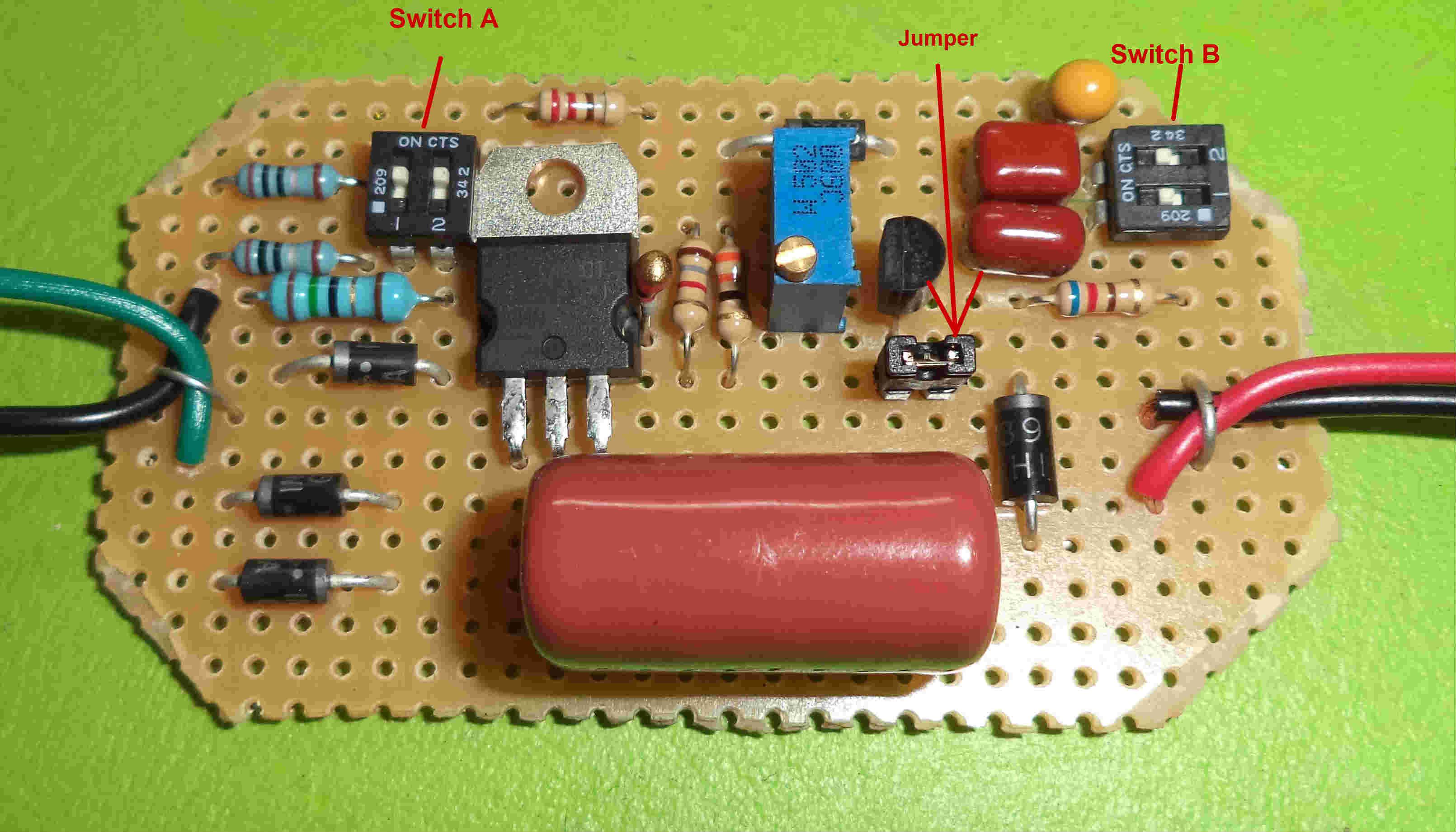 DETERMINING BEST SWITCH SETTINGS: Test the settings for your bike to see what works best. Jetting, porting, compression, and exhaust pipe all affect the needed timing. Start with the A switches: test for the best of the 3 input resistances (15, 16, 17ohm). You can test going up hills at low RPM (around 4000) to see which A setting gives the most torque and acceleration. Test switch B for best acceleration on a level road above 5000 RPM. Which ever switch setting allows the best acceleration is the setting you should use because that indicates best harmony between the timing curve and engine/pipe.  HOW TO UTILIZE THE SWITCHES: Just remove the
boxes 4 screws with a small Phillips screwdriver. If your screwdriver
doesn't fit in the screw head properly then it will slip when turned.
Don't go any farther if this happens. Go directly to a store and
buy a fine-tipped screwdriver that will work properly. Otherwise you
will ruin the screw heads. Once the box lid is removed you can see the
two switches and jumper. You can use your
fingernails or a small screwdriver or
something to manipulate the switches. The jumper can be pulled off with needle nose pliars. |