And My Excel Calculator There are many contributing factors to the combustion burn rate which should match the target RPM (which is lower than top RPM for street and trail bikes). The idea is to have the combustion mostly complete before a certain crank degrees at the target RPM. The contributing factors are carb size, jetting, compression ratio, cylinder bore, gas octane, and squish velocity. 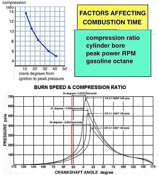 I found out that the old formula people have used to figure out the correct carb diameter is .8 x square root(cc x RPM/1000). That formula and any carb sizing chart are just over-simplifications for the non-technical public. 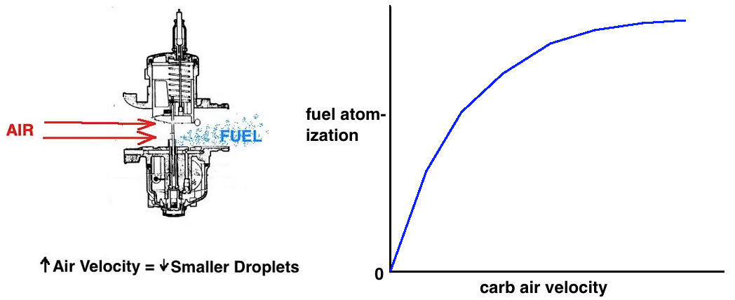 More velocity atomizes the fuel more which increases the burn speed. More compression increases the burn speed. High squish velocity increases burn speed but I doubt manufacturers use that trick much because it also contributes to detonation. If you are wanting the best carb for racing then consider how much time you spend at the last 1000RPM of the powerband. A racing sized carb would be good for that but for anything else then consider a smaller carb which will help out with mid range power. Sometimes the crispness of the power exiting corners is just as important as the top RPM power. Surprisingly, carb air velocity at the needle is not a linear increase with RPM. Since the only two variable factors both contribute to a faster burn as they increase, then it's easy to average them together (see green graph below) to get an idea of their combined effect. The graph of their combined average shows a steady increase up to max RPM. 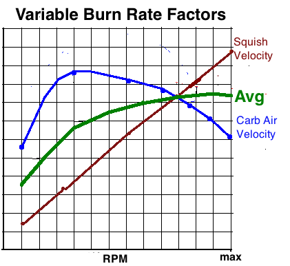 Below is a screenshot of the Excel spreadsheet. To use it just enter the needed data into the light blue cells and the calculated results will display in the other cells. For reed valved engines the best carb size for street/trail is at G11, and the best carb size for top RPM racing is shown at H11. Large carbs produce more large fuel droplets which cool and lubricate better which is important to race bikes. And smaller carbs give better economy although they tend to let the engine run hotter. The graph shown is only for engines with reed valve, although the basic calculation for carb air speed is available for engines with piston port intake at E14 (after you enter the intake duration at A13). The time of sucking in air/fuel is about half as much with piston port intakes and so the carbs should be bigger to keep the air velocity from being too high in the carb. The graph is only set for reed valve intakes, not piston port. It's a task I need to work on. 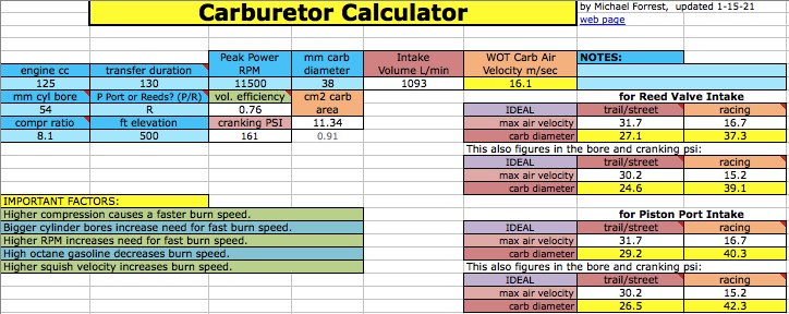 EXAMPLES: Honda CR500: Honda equipped it with the same size carb as their 250, a 38mm. The calculator recommended 37mm for trail use, and 39mm for racing. 38mm is a good all-purpose compromise. Also consider if the carb is a round or flat slide. Round slide is better for trail riding because round slide carbs aren't excessively rich mid throttle, whereas flat slide carbs are inherently that way which is good for racing but bad for trail riding. 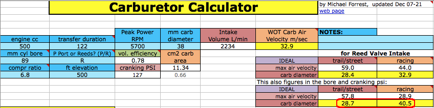 Honda CR250: The calculator shows a 38mm carb would be best and Honda uses a 38mm. 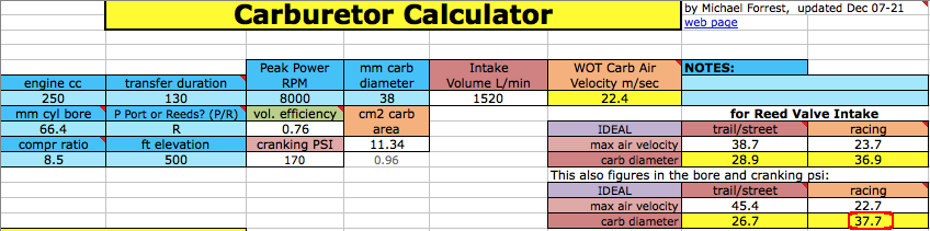 Honda CR125: The calculator shows a 37mm carb would be best and Honda uses a 38mm. Notice with a 36mm (top data below) how the air velocity only just barely is beginning to get in the red zone. Stank Dog, racing a Husqvarna TC125, says he prefers the 36mm carb. 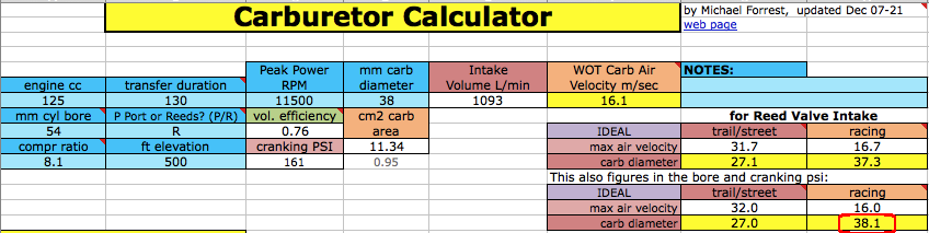 I went on some forums and asked for full data on peoples rides if they had experimented with different carb sizes for the highest power. Here are three examples: 2 cylinder 250cc for karting: I'm not sure which specific engine he has but karting engines are set to rev high and need big carbs. He selected the 42mm which my calculator says ideally should be 39mm or 40mm (39.4mm). It shows only half of the engine (125cc) which is how it's done.  RD400 (2 cylinder): The calculators recommended 39mm is pretty close to his selected 38mm. This bike was modified with pipe, big carb, and higher compression. The owner said it had been bumped up to a compression ratio more than 9.1:1. He said top RPM was 10K so I'm assuming peak power at 9K RPM.  Honda NSR50: The stock carb was a 20mm but someone put a 28mm carb on it, which you can see here was OK but what my calculator recommends is 24.9mm for racing, so a 24mm is closest to that. The top data set (below) is for a 20mm carb which shows it is OK for moderate street use. 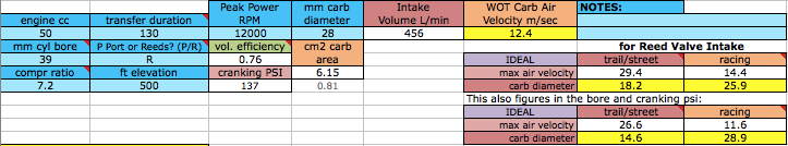 This graphic illustrates the realtionships between carb sizing, atomization, and ideal top RPM for carb size. 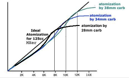 Click here to watch my Youtube video on this subject. Reed Valve CalculatorNow the Carb Calculator comes with a reed valve calculator on its sheet 2. With it you can compare reed valves, virtually try different reed materials (carbon fiber, fiberglass, steel), and try out the modification of removing the valves ribs along with making your own reed petals. See my Youtube video about it. Here's a screenshot of this calculator. If the graph has a red area like this graph does, then that means the flow area thru the valve is too small which is causing too high a velocity of air/fuel thru it. This happens when the valve is undersized, or the curved reed stop needs to be removed (enter "N" at B17), or the reeds are too stiff and either need to be thinner or of a softer material. But also make sure the max RPM (at B18) of the reeds isn't less than the top RPM you entered at H21. If the max RPM is lower, then the reeds may flutter at top RPM and cause a power loss. You can make your own reeds, and the different materials available to make them are listed below the graph at J46. 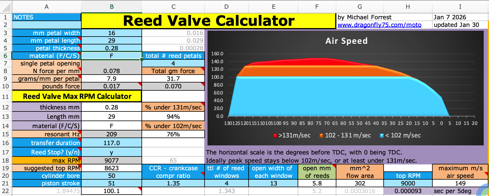
Click here for my 2 stroke calculators list (including this one) and how to buy. Below are all the hidden comments in the spreadsheet in case your computer won't let you read them all. Sheet Cell Comment Text Carb $B$3 This is the calculated transfer duration based on the height above the port. It is the hot value which is slightly less than the cold value but is more accurate for calculating carb air speed. Carb $G$3 Latest updates: Pipe Back Pressure Calculator at the bottom, warning when carb is too small and causing too high air velocity, reed valve calculator added on sheet 2, carb speed graph now accurately calculated, reed calc refined to match reality Carb $A$4 This is the mm above the highest transfer or boost port, from it to the TDC point on the cylinder (where the top piston edge is at TDC). If you don't know this distance but do know the port duration then, after entering conrod length and stroke, look below G104 for the mm above port that matches the duration. This affects the average air velocity, but since the calculator was changed to key off the peak velocity this input is ignored. Carb $B$4 This is the center hole distance in millimeters. Typical is 2x the stroke length. Carb $C$4 Possible transfer duration based on RPM Carb $C$5 This is usually around 1000 RPM below the top RPM of pipe boost, the end of the powerband. If you want to know the max velocity then enter the end of powerband RPM here. Carb $F$5 Air velocity averaged over the complete crank cycle of 360 degrees, not the peak velocity. Carb $A$6 The pistons swept volume in cc. Carb $B$6 If you don't know it and you don't know the mm above port then enter 125 for racing or 117 for street/trail riding or use the estimated duration calculated at C4 based on RPM. If you know the mm above port then enter that at A5, enter the piston stroke at A11, and get the estimated duration from B3 (that comes from C116). This affects the average air velocity, but since the calculator was changed to key off the peak velocity this input is ignored. Carb $A$8 Cylinder diameter Carb $C$8 this is by the volume the piston displaces from transfers closing to TDC Carb $E$8 This is the air velocity that happens between "transfers closing" and TDC. Over 102m/sec causes an increase in crankcase vacuum which maintains that peak velocity longer than the normal midpoint between transfers closing and TDC. But if the calculated peak is more than 144 then the flow will continue past TDC which reduces the crankcase pressure at the time of transfers opening which reduces the transfer flow speed into the cylinder which in engines that have too high a CCR is actually beneficial. To see if the "too high velocity" warning displays at E10 you need to enter the top RPM at C7 instead of the peak power RPM (if the two are different). Carb $G$9 Good mid range power is very important to trail and street bikes. The RPM zone this targets for best power is about 55% to 78% of the peak power RPM at C7. Carb $H$9 For emphasis on top RPM power, the last 2000 RPM. Carb $I$9 This is the range for the carb size entered at D7. Carb $E$10 If the "too high velocity" warning displays here then the carb size needs to be increased if you want to improve peak power. Carb $B$11 Calculated engine cc according to bore and stroke. Carb $E$12 This is the average speed of the air velocity that happens between "transfers closing" and TDC. Without the return suction wave from the pipe (at high RPM) the intake flow through the reed valve begines at transfers closing. Carb $I$12 If the carb diameter is between the recommended minimum and maximum then this shows the % it is at from 0% being the minimum to 100% being the maximum. So if the recommended sizes are 10mm minimum and 20mm maximum and the carb size is 16mm then the % will show 60%. Carb $A$26 Combustion speed increases with more carb air velocity (due to more atomization of fuel), higher squish velocity, and higher engine compression. They need to counterbalance each other. The large bore engines typically were made with too much squish velocity and so the detonation was reduced by changing the squish band for less velocity. If they put in a larger carburetor then that mod would of been less needed. Carb $L$28 Enter 3 if the pipes diffuser has continuously increasing cone angles from end of header to beginning of belly. Carb $L$29 If unmeasured then leave at 600. Typically the lower the exhaust port duration, the lower the EGT. Carb $K$31 seconds of 1 crank rotation Carb $L$31 The end RPM that you normally wind the engine out to. After you see the ideal intake length and you want to know the resonant RPM for the intake length that your bike now has then just keep changing the RPM till until your current intake length is displayed at J36. Carb $K$32 seconds EO to BDC Carb $L$32 This is usually about 1.5 degrees less than the cold value due to the conrod elongating with heat. Carb $K$33 seconds BDC to TC Carb $L$33 "This is usually about 3 degrees less due to the conrod elongating with heat. " Carb $L$34 Millimeters from exhaust side of piston to the beginning of the diffuser cone. Carb $L$35 If the cylinder has a boost port that connects to the intake port then enter Y. Carb $K$36 Ideal intake length if going by the second diffuser peak of a two cone diffuser. Carb $L$36 Length from piston face to beginning of opening of carb bell. Carb $L$37 This is the time after exhaust port opening when the beginning of the reversion wave comes back to the cylinder. Carb $K$38 Milliseconds from exhaust port opening to transfer port closing. Carb $L$38 The return diffuser wave is inversed at the carb bell to become a pressure wave. This is the time from exhaust port opening to when the peak of the reversion wave reaches the cylinder. This should equal the time of transfers closing so that the delivery ratio in the cylinder will be increased. Carb $L$39 You can enter your current intake length here to see how far J40 is from H38. Then keep changing the RPM till H38 equals that value. That is its resonant RPM. Carb $B$95 Inner diameter in millimeters. To convert inches to mm just multiply inches by 25.4 Carb $D$95 Stinger cross sectional area in square cm Carb $B$96 If a silencer is attached to it then enter the length to where the pressure pulse first starts expanding (such as at the tube holes in a racing silencer). To get milliimeters just multiply inches by 25.4 Carb $D$97 Base back pressure without stinger but with the baffles exit hole of the same diameter as stinger Carb $B$98 The higher the PSI, the more the dynamic engine compression is, but the lower the delivery ratio is. An average value at high RPM is 1 to 2 PSI, with 3 PSI benefiting some race engines that only use the highest RPM. It's OK to have less than 1 if low RPM power is the most important. The more limiting the reed valve or carb is, the lower the back pressure needs to be. This pressure value is calculated for the RPM entered at C7. Carb $B$108 This is to the TDC point which is equal to the distance to cylinder top and then subtracting the deck distance. Carb $A$125 degrees BTDC REED VALVE COMMENTSReed Valve $A$4 "Length doesn't include the beginning of the reed petal that's secured firmly onto the housing. Measure all its free length in millimeters. " Reed Valve $A$5 Measure this with digital caliper. Typical thicknesses are listed at J46. Reed Valve $A$6 "Enter F for G10 fiberglass, C for carbon fiber, or S for steel. " Reed Valve $A$8 Calculated force is in Newtons. You can compare this calculation to reality by hanging nuts on a string tied to the end of the reed petal. Add weight till the petal opens 1/10 of its free length. That would be 3.6mm for a 36mm free length. Then divide that weight by the opening mm to get force per mm. Reed Valve $C$8 Total grams force of all petals added together. Reed Valve $A$9 This calculator seems to say that twice the force is needed to bend a reed petal when it is made with twice the width. But that is compensated for because reed opening is the result of vacuum per sq mm divided by reed stiffness. If you redesign a reed valve to have one petal replace two, and the flow area of the pyramid housing remains the same then the area of vacuum wave acting on the reed petal doubles and so still opens it as much as before. If you make your own single reed petal to replace what was a double or triple one then the force needed to open it increases just a little due to the small increase in fiber width since before there was free space between petals and now there isn't. Reed Valve $B$10 Pounds force for each reed petal. Reed Valve $C$10 Pounds force of all reed petals added together. Reed Valve $C$12 The orange and blue zones represent the normal zones. A good reed valve minimizes the red zone which is above 131m/sec air flow thru the valve under the petals. That excess speed causes an excess pressure difference before and after the valve. Reed Valve $A$15 # of full cycles per second of an oscillating reed petal that is allowed to swing in both directions. It has the maximum swing at this frequency. Reed Valve $A$16 Enter the degrees the transfer ports are open every cycle. If they are staggered in height then enter the degrees of the highest one. Reed Valve $A$17 Y is for "yes there is a reed stop/limiter", and N is for no. If the limiter has little effect on the reed opening then just take the average of the two max RPM's using Y and N. Reed Valve $A$18 There's a possibility the reeds will cause a loss of power at this RPM and above. So it is better to use reeds that give a max RPM higher than what your engine revs to. If you are designing your own reed valves then you can play with reed length as well as material thickness to get the desired RPM. Reeds flutter at RPM even higher than where power loss begins to happen at. Reed Valve $A$19 This is 95% of the above RPM. Higher is OK as long as the reeds don't flutter. There is some variation between reed material from different manufacturers so these calculations aren't to be considered perfect. Reed Valve $F$19 The estimated distance the reeds are pulled up off the housing during WOT flow. The factors involed are: calculated engine vacuum at the reeds, total window width, reed tension. Maximum allowed is .27 x the free reed length at B4. Reed Valve $C$20 The normal range is 1.3 to 1.5, with the higher the number, the higher the max RPM of the engine and the smaller the engine. Typical is 1.3 for 500cc reving to 8000 and 1.5 for 125cc reving to 11K. The RPM is more important than the engine size. Reed Valve $I$20 thru each window. The higher the speed over 102, the more the vacuum drop across the valve. Reed Valve $B$22 engine cc |