|
My Crank Balance Tests I had two different 55cc engines using different cylinders and pistons. One was with piston port intake and the other was reed valved. The results I got testing those, along with online calculators for upper piston assembly inertia force and the centrifugal force of the counter balance is what I based my old theory of balancing on. The piston port engine was way off in balance, and the other was perfectly balanced. Using it as a base point I developed an Excel file for calculating the rotational forces on the crankshaft which allows you to input different counter-balance hole sizes till the numbers are right. In calculating the offsetting centrifugal force of the imbalanced flywheel we treat the weight removed by the flywheel holes as an additional weight because on the opposite side of the flywheels there exists that additional weight. For example, if you removed the flywheel and put it on two weight scales you will see that the non-holed side has weight in excess of the holed side equal to the actual weight removed when the holes were made. So we use that "missing" weight to make the centrifugal force calculations. 1st test: 2nd
test: In
figuring the counter balance weight it's important to include
everything that
would affect it. As example: my flywheel came with two 11.5mm diameter
holes through both flywheels. The stainless steel there removed adds up
to 50 grams. The conrod pin added 3.3 grams after the weight of the
conrod pin holes weight were subtracted from it. Its weight was only
calculated using the steel weight calculator, not
measured. The part of the conrod that is around the bearing, and the
bearing itself, weigh around 30 grams. The centrifugal force has to be
figured at the distances of 19mm of the conrod pin, 36mm of the
additional
balance hole, and the distance of the two counter balance holes. 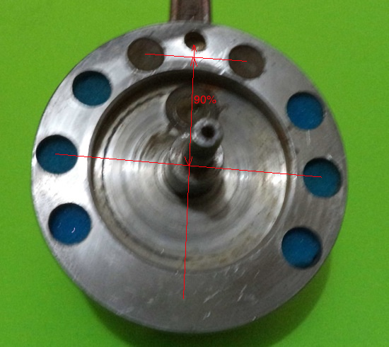 Concerning determining the weight of the lower conrod bearing and the part of the conrod that is around the bearing: I figured that by dipping the two into a measured amount of water and seeing how many cc (ml) they raise the water level and then multiplied their ratio by the total weight. My 48cc rod end with bearing had an equivalent 30 grams. You can drill extra balance holes
with any good electric drill although it's a bit tough. Much easier to
take it to a machine shop and let them put it on a drill press. Also
the holes can be drilled at the TDC location of the crank wheels
without even taking it out of the crank cases. Just put duct tape on
the crank wheels (after cleaning them with alcohol) to keep metal
shavings from going into the crankcase, and then keep the crank in
correct position by using vise grips on the primary gear above and
below where it meshes with the clutch gear. You can measure from
halfway through the angled tip and mark the drill bit at the correct
distance with black electrical tape. That way you have a visual
reference while drilling. |