|
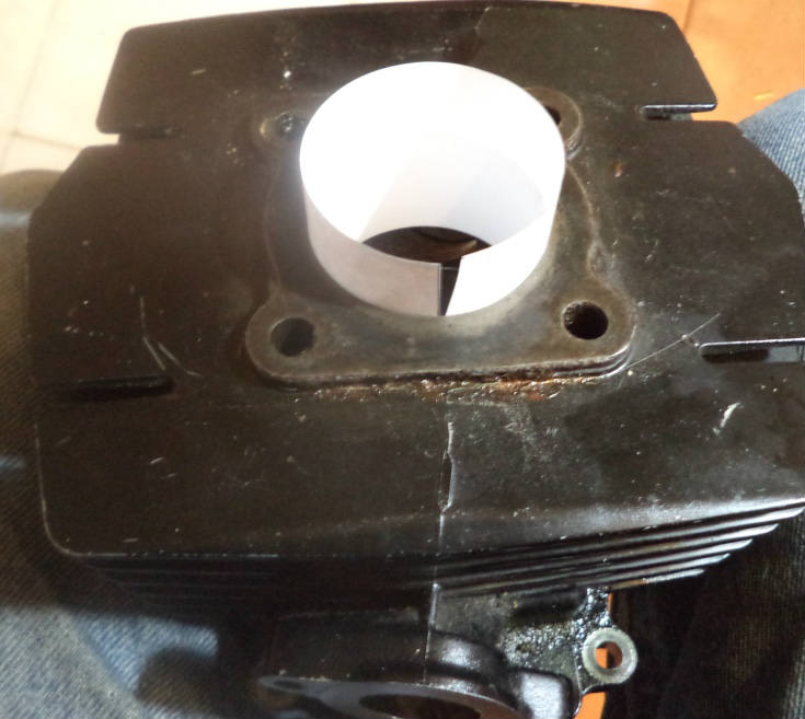
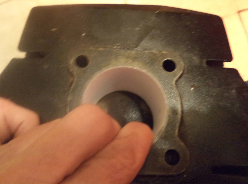
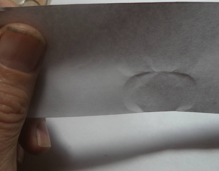
My quick usage overview video: Using ECcalc30 The heart of the program, the pipe return waves graph on sheet 3:  Look at the bottom left of sheet 1 to see the 4 sheet tabs. You go to the desired sheet by clicking on its tab. The design steps are listed on sheet 1. 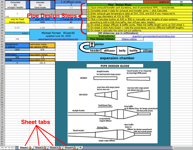 Here is sheet 1 where you will enter the basic engine data. Each row corresponds to an RPM (C5-C13) with the # at C5 corresponding to the end of the pipe powerband. The sequence of calculations and #'s displayed continues for rows 6-13 at rows 19-26. The basic design steps are listed at the bottom under "Pipe Design Steps". At D6 is calculated an approximate exhaust pulse time duration based on engine specs and exhaust port area on sheet 4. This affects the return waves durations. Getting this exactly right is impossible without the expensive pressure trace equipment that race teams use but you can get close here. For example, the difference between a .8ms and .9ms exhaust pulse (a 12% change) is only a 5% time span difference in the return diffuser wave so this calculators approximation is good enough.  Step #1: It's best to get paper traces of your ports for the most accuracy but ECcalc30 can do a decent job of guesstimating the port size and resultant exhaust pulse time just by knowing the cylinder bore, how many exhaust ports there are, and their max widths. If you aren't going to measure the port widths every millimeter down then on sheet 4 just enter the # of exhaust ports at I6, enter the widths of exhaust ports at I2 (only for triple exhaust) and I4 and then just click on the CALCULATE button and the calculated values will appear at the J column (rows 10-43). Estimated values are ok for pipe designing but not so good for evaluating porting needs (listed farther down the same sheet). The exhaust port shape is graphed there but it is sideways (90* CCW) which is the easiest way for me to represent it since some seemingly simple things are hard to do on Excel. 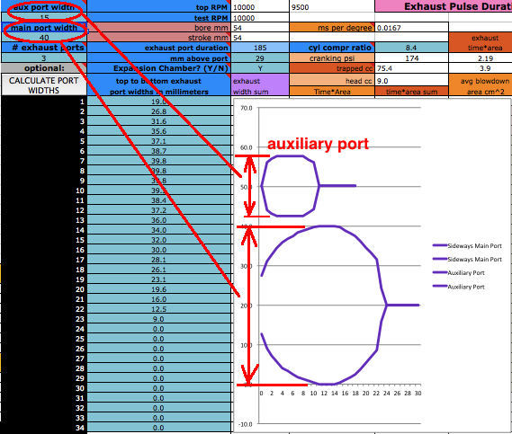 For the most accurate results start by making an imprint of your exhaust port with paper inserted into the cylinder. Align the edge of the paper at the top edge of the cylinder and press onto the paper along the edges of the port(s).  How to get the port trace: With cylinder removed... Just cut a rectangle of paper as tall as from the cylinder top to a bit beyond the bottom of the port. Its width should be a bit more than the cylinder diameter multiplied by 3. Insert the paper into the cylinder so that its top edge is even with the top edge of the cylinder. With cylinder on bike but head removed... Just cut a rectangle of paper as tall as from the cylinder top to the piston edge with the piston as low as it will go. Its width should be a bit more than the cylinder diameter multiplied by 3. Insert the paper into the cylinder so that its bottom edge is even with the top edge of the piston. Then spread the paper apart so it is pressing against all of the cylinder and then hold it in place where the paper overlaps itself. Then reach in and press your thumb onto the paper where you think the top of the port is. Once you can feel the top edge then press hard on the edge without pushing the paper into the exhaust port. Do this all along the exhaust ports edges. Remove the paper and enhance the trace with an ink pen. Mark along both sides of the ports every 1mm and use ruler and pen to connect the marks. Then use your ruler to measure each port width for each 1mm and write them down as illustrated above. It's not necessary to go all the way to the bottom of the port. Here's pics showing what I'm describing...
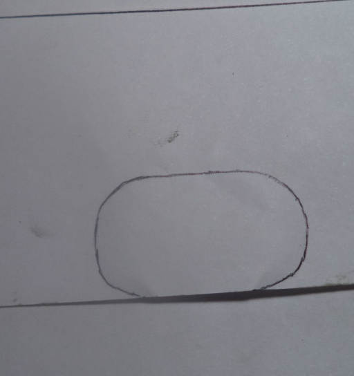
Measuring from the top edge of the paper, make horizontal marks to the left and the right of the exhaust port(s) every 1mm. Then draw horozontal lines across the exhaust port that are spaced 1mm apart as you see in the graphic below. Measure the center millimeter width of each 1mm space and write it down. If there are two or three sections along one line then add their widths together. For example if the main port is 40mm and each auxiliary port is 10mm then the total is 60mm. 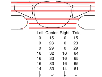
[In the following screenshots I often border the input cells that I'm talking about in red.] Manual Exhaust Port Measurement Entry On sheet 4 starting from the top width to the bottom width enter all the exhaust port widths (for every 1mm down that you previously wrote down) into the spaces at sheet 4 from J10 to J43. Also enter the exhaust port duration, engine compression ratio, and mm above the exhaust port from the port top to the TDC (top dead center) point on the cylinder (where the top edge of the piston is at TDC). 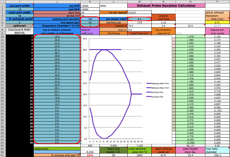 At the lower left of sheet 4 is a mini calculator that shows the mm above port for the exhaust and transfer ports based on the engine stroke and the conrod length. Use that or an online port duration calculator for the "mm above port" entry at K6 and K53. If you measured the cold above port distances then enter them at A50 and A52 to see what the estimated hot distances are. (They are more due to TDC raising with hot con rod extension) If you used my method for finding the hot distances then use those in the online calculator to find the durations.  Step #2: On sheet 1 enter the port durations (read how to measure to find the hot durations for highest accuracy) and end RPM of the pipe powerband (at the end of being "on the pipe" which is usually about 750 RPM above peak power RPM) at C5. The RPM you enter at C5 should not cause more than a 25meter/second piston speed displayed at D12 and a warning will display at D13 when it exceeds that. When entering RPM do not type in the comma. For example enter 9000 instead of 9,000. The port "duration" refers to how many crank degress the port is open each crank revolution. It's best to determine them by using an online calculator and the port heights (instead of using a degree wheel which is inaccurate because it's hard to see when the top edge of the piston is level with the top edge of the port). If you haven't used my method to calculate the "hot" durations then subtract 2 degreess from the exhaust duration and 4 degrees from the transfers duration. That's the typical difference between hot and cold. 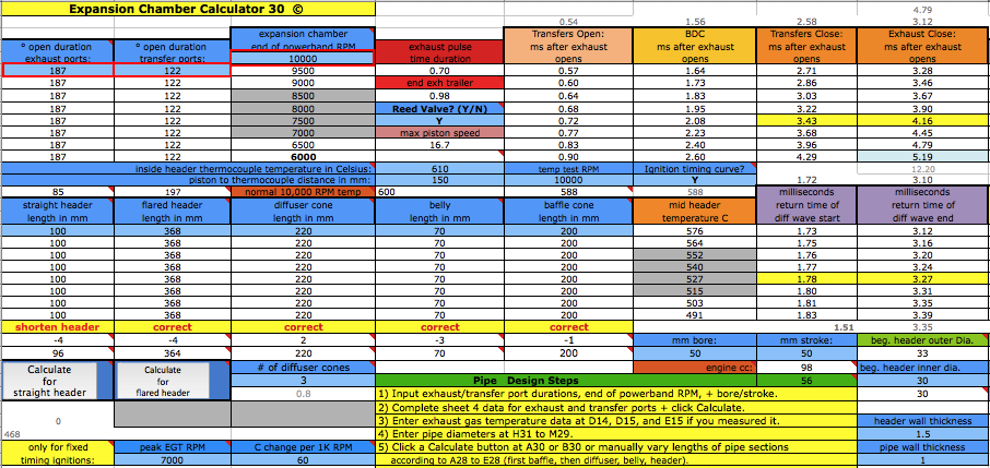 The RPM you enter at C5 corresponds to the very end of the pipe powerband, a bit higher than where you would normally upshift. The graph below shows a pipe powerband of 2250 RPM. So with the example below the end of powerband RPM is about 750 RPM more than peak power RPM. So if you know the intended peak power RPM just add 750 to it to figure the end of powerband RPM. But be aware that some CDI have max RPM limiters if you are wanting to mod for higher RPM. 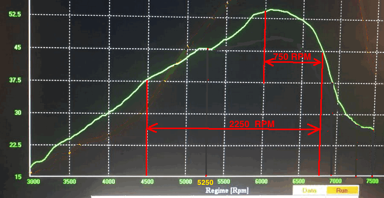 At D10 enter "Y" (for yes) if your engine has a reed valve intake or "N" if it doesn't. At F15 enter "Y" if your ignition system varies the ignition timing with RPM (like any normal modern CDI does), or "N" (for no) if it has fixed timing ignition (such as was on all old bikes such as the old Husqvarna and Maico motocross bikes).  Step #3: If you don't know the exhaust gas temperature then just leave these 3 values as they are. Or you can find it out by analyzing your current pipe if you know the beginning and ending pipe powerband RPM. If the power graph of your pipe/engine on sheet 3 is higher in the RPM range than what you know is true for your pipe then lower the temp at D14 till the graph matches reality. (and vice versa for the opposite) If you measure it then enter the exhaust gas temperature in Celsius at D14 (click here for a farenheit converter), distance from piston to thermocouple at D15, and RPM of test temp at F14. If you don't know what it is then just use 600 at 10,000 RPM at 150mm. The best way to know the exhaust gas temp without measuring it is to ride the bike with a speedometer on it (which can be a bicycle speedometer) and note the speed when the bike is at peak power. Then use the gear ratio calculator to figure out at what RPM that happened. Then fill in all of sheet 1, 2 + 4 and on sheet 3 click the Auto-Graph button at H185 to see the peak power RPM. Then keep adjusting the temperature at sheet 1 D14 and clicking the Auto-Graph button on sheet 3 till the graph matches reality. Where many people screw up is by not correctly jetting the engines previous setup to know its end RPM or peak power RPM. Most people jet by spark plug color which is horribly wrong. You have to jet for best peak power. Go to this page to read the full sequence.  How to use the Gear RPM Range Calculator: Go to sheet 3 and scroll down below the pipe power grapher to see the Gear RPM Range Calculator. A) Measure your rear wheels outer circumference: Push the bike till the valve stem is at the very bottom. Mark the ground next to the tire equal to where the stem is. Sit on the bike and roll forward till the stem is once again at the very bottom. Mark the ground there and measure the distance between the marks. If you measured in inches then put that value at J231 to know the equivalent distance in meters at K231. Enter the wheel circumference meters at G231. B) If you leave G229 blank then this calculator will use the end of pipe powerband RPM from sheet 1. Otherwise it will use whatever RPM you enter there. C) Put the bike in 1st gear. Take off your ignition cover and prop the bike up so the rear wheel is off the ground. Take the spark plug out. Spin the wheel till the valve stem is at a spot that you can easily remember (such as visually at the top edge of the swingarm.) Mark the flywheel and the cases so the two marks align. Slowly turn the rear wheel while counting the complete turns of the flywheel. Do this till the valve stem returns to its original position. A sloppier but easier way is to hold a pencil in the spark plug hole and count the times the piston hits it. Write down the crank rotations per wheel rotation and put that number for each gear from G237 to G242. D) Take note of the RPM spread in the K column of 2nd gear. Your pipes powerband should be at least that wide. To find out the RPM for a certain bike speed (KPH or MPH) just keep entering different RPM at G229 till the right speed is listed for the right gear. (the speed in a certain gear you experienced)  This is important to know to make sure your pipe powerband is longer than the longest gear RPM spread. On my 4 speed 100cc I had to resort to an odd design because the longest pipe powerband of normal expansion chamber was just barely long enough for the gear RPM spread and so I had to upshift at just the right RPM or a little higher or else it would be out of the pipe powerband which is deadly on a 100cc. Needless to say it wasn't any fun having to be so precise all the time. Click here to read about the unusual design I had to use. Step #4: On sheet 1 enter the stinger inner diameter at L32 if you don't want to use the size displayed at L31. That recommended size will be used if you keep L32 blank. Look at the comment hidden at N30 to see common available inner pipe diameters for use as stingers (from Metals Depot):  Enter the pipe inner diameters at H31 to J31. Enter the metal thicknesses at H35 and H37. All these dimensions are important to figuring out the approximate gas temperature inside the pipe which affects wave speed. The temperature decrease along the pipe is calculated by the outer area as the "dissipator" of heat. The max belly diameter at K31 is not a strict value but it's a good average max.  Designing a New Pipe Step #5: If your Excel can use macros then just click the calculate button for the right lengths to be entered into A19 to E19. When calculating for pipes with flared headers you need to first enter the distance from the piston face to the beginning of the flared section at A19. This value won't be changed when you click the Calculate for Flared Header button. If these calculated lengths are incompatible with the available space on your bike then you can change the top RPM but keep in mind that single cylinder cranks are tuned to a certain top RPM and the farther you stray from that the more vibration you will have at top RPM. But of course you can use my crank balance calculator to know how to retune it. Which beginning pipe design? 1. A flared header with single cone diffuser is for race engines with around 1.5 crankcase compression ratio (CCR). That ratio causes a strong suction pulse to the carb and needs little help from the diffusers suction wave. The minimal diffuser wave allows over-rev if the CDI permits it, although it does reduce peak power. A typical flare angle is 1.5 degrees. 2. A CCR from 1.3 to 1.4 needs a straight header and 3 cone diffuser which prevents over-rev but gives the best power due to increasing intake flow due to a strong return diffuser wave.  Step #6: The next step on sheet 4 helps determine if there is enough blowdown area/time to keep from limiting top RPM power by limiting the intake charge transfer to the cylinder. Scroll down a bit and enter the total transfers width at K51 which is the width of all the transfers (measured about 2/3 down from the top of the transfers) and half of the boosts total width added together. Typical values are 54% of the cylinders circumference (bore x 3.14) for 4 transfers and boosts, or 40% of it for 2 transfers and boosts. Those two calculated widths (useful if you don't know the width of your transfers) are at L51 and L52 which you can enter at K51 if you know the transfer arrangement but haven't measured the widths. Enter the transfers duration at K52 and then at K53 enter the distance from the top of the transfers to the "deck" (where top piston edge is at TDC) point on the cylinder. Then click the CALULATE button and note where the blue graph crosses the 1.0 line which indicates the peak power RPM of the engine porting as if it didn't have an expansion chamber. In this example it is just right if you want the highest peak engine power (at the expense of a meaty mid-range). The transfers total width, duration, and when the exhaust pressure overlaps the transfers (7000 RPM in this case) all affect the engines peak power RPM. I've analyzed race engines with 0% overlap at K47. If the overlap is more than 10% and your engines PPRPM is too low then you need to raise the exhaust port. If it is less than 10% but the PPRPM is too low then you need to raise both the exhaust and transfers. 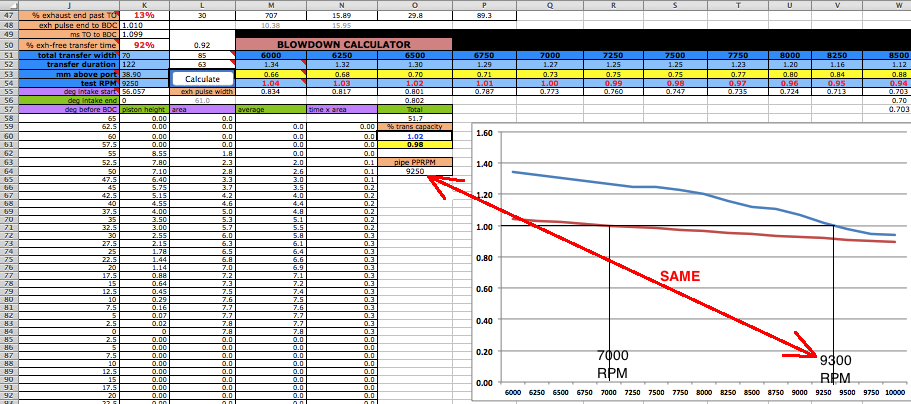 Step #7: On sheet 2 you can let the sheet automatically create the diffuser dimensions or you can manually enter your own. Just put an x at F39 for it to automatically calculate for you a diffuser. Then select at G45 to G47 what type of diffuser you want. The beginning diameter and angle for the 1st cone are at C46 and C47. For the 2nd cone at D46 and D47, and for the 3rd cone at E46 and E47, and those are all transferred to a section to the right where they will be transferred to sheet 3 to be used in the creation of the diffuser return wave. If you want to change the total diffuser length, beginning diameter, or belly diameter then do so at sheet 1. If the desired cone length exceeds the range of 80mm to 440mm then you have to put an x at F40 and do it all manually.  For manual diffuser creation of a 3 cone diffuser outside of the range of 80mm to 440mm you can still use the values created in the mini calculator. First make sure the space at F39 is blank and then enter an "x" at F40. Then enter the three diffuser angles into C7, C17, and C27.  Then enter the two beginning cone diameters from D47 and E47 to B17 and B27. The mini calculator says the first cone is 30mm long, the second 20mm, and the third 20mm. So then enter the first 3 pressure change #s from row 12 to the M column for the first cone. Then the first two change #s from row 22 to column M. Then the first two change #s from row 32 to column M. Make sure all other cells in the M and N column have 0 in them.  Or you can use the cone calculator at B37 to B40 to design your own diffuser one cone at a time. Here's a look at what the negative diffuser waves look like with the 3 diffuser designs.  Now we can calculate the baffle cone. Usually a single cone is good enough but you can also virtually try the other two types to see how they all compare on the power graph. Sheet 1 usually gives the right cone length for a good form of powerband and good power. If the new return wave strength increases very much from the previous design then usually the timing needs to be retarded some. Decreasing the baffles length to increase the wave strength also shortens the pipe powerband a little. The automatic option allows you to choose what you want and not have to touch anything else. Just put an X at the desired section and everything will be done for you. It uses the baffle length from sheet 1 E19. You can see the single cone angle at B88 and the details for the other two types are to the right of the selection cells. 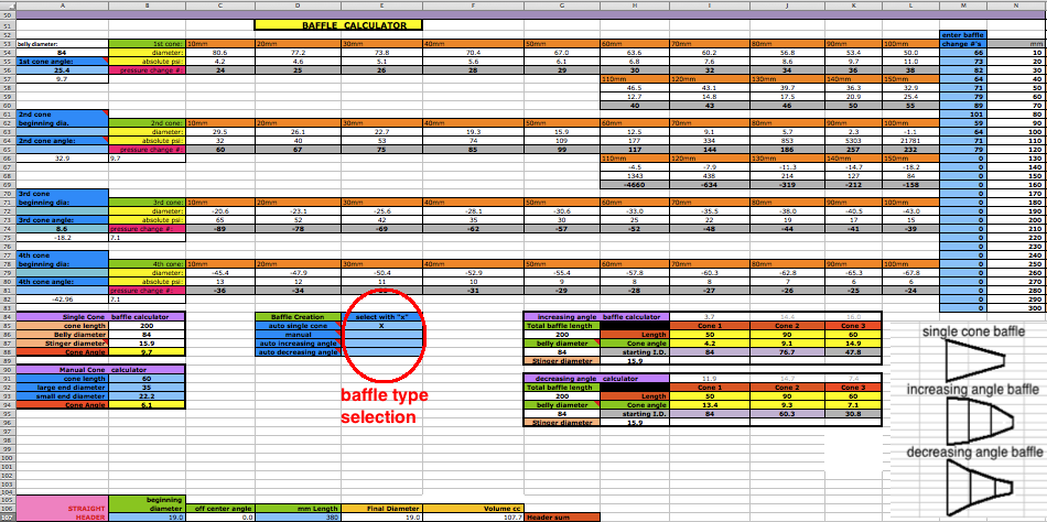 If you want to manually create a baffle then use the manual calculator for your own design (if it isn't a single cone). Or just one of the 3 cone designs presented on this sheet. Sometimes the increasing angle baffle gives an increase in average pipe power so I will show how to do that. First enter the calculated cone angles into A56, A65, and A74. 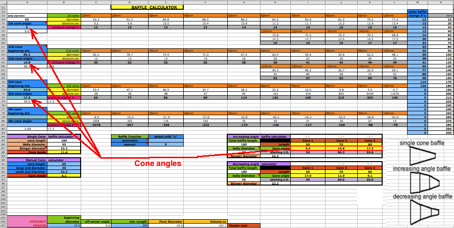 Then enter the beginning diameters from J88 and K88 into A63 and A72. That's all that is needed. The program then takes the pressure change #'s and enters them in the column that will be read by the return wave simulator on sheet 3. 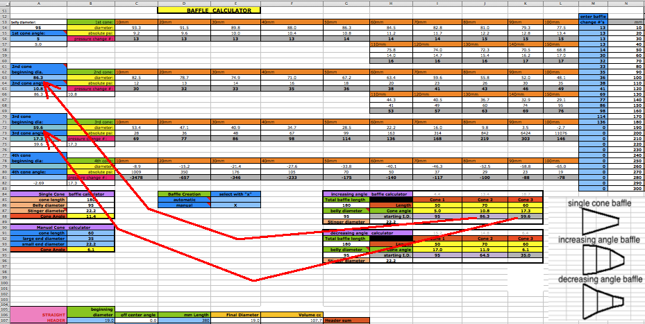 Pipe Power Calculator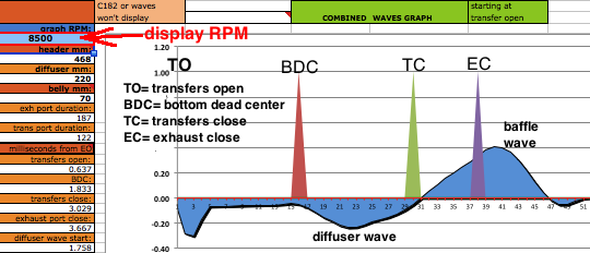
The whole point is to have the best pipe powerband (graphed power height and width). After entering the estimated peak horsepower at I186 just click onto the Auto-Graph button and the calculations will display the resultant pipe powerband below the return waves graph. 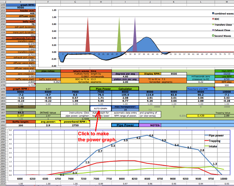 Power Factors: The intake is determined mostly by the average height of the diffuser wave, how much of the time it occupies between BDC and TC, and the pressure a fraction before TC. The exhaust trapping is determined by the pressure at EC and mid TC-EC. Those two graphs are multiplied together to get the power. 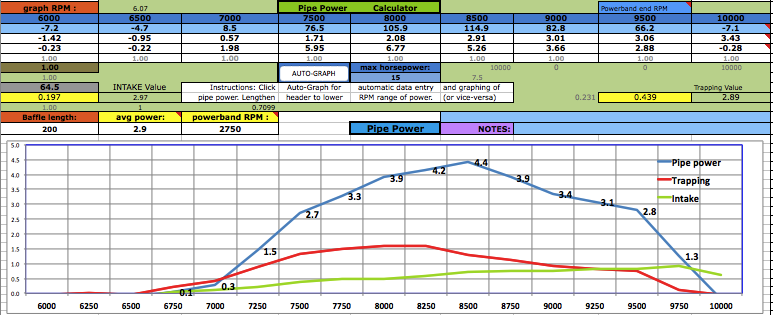 Trying Variations: It is good to record the results of the current pipe design and then try a couple variations and record each ones result. In this example I shortened the belly by 40mm and the power increased but it shortened the powerband a bit. (You can't create energy, just move it around). You can change the header or diffuser length on sheet 1 to move the powerband up or down on the RPM scale. And changing the belly length will change the powerband shape a bit. If you add 20mm to the belly then subtract the same amount from the diffuser. If you've selected manual diffuser design on sheet 2 then you need to re-do it there after any diffuser length changes on sheet 1. For more over-rev and less peak power increase the belly length. For a wider powerband increase the diffuser/belly/baffle and decrease the header so the same distance to the baffle remains. 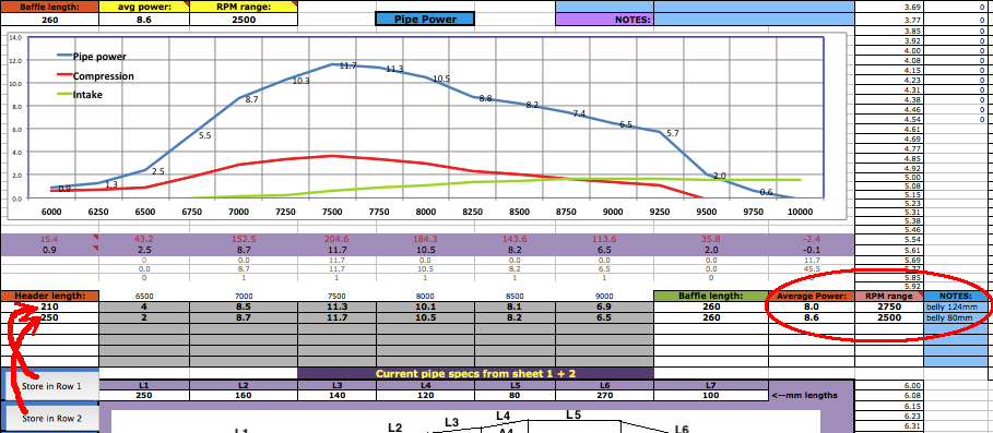 With your pipe design finished you can go to sheet 4 to know how to cut out the patterns from poster paper which you can then trace onto the sheet metal (.7mm or more thickness) before cutting it with tin snips. You'll need an extra long ruler. This sample pipes data has been entered in the cone making section below for you to see how its done.  Every diameter needs the sheet metal thickness added to it which is done for you at A38 to C42. That section shows the calculated 3 cone diffuser values and the values for a 1 cone baffle. For anything else you need to manually enter the values into the light blue cells at A29 to C34. Make sure you add in the sheet metal thickness to all the pipe diameters you enter starting at A29. After entering the data in the blue cells then use the calculated data at D29 to H34 to draw the graphics pattern on poster paper. The gray area of the graphic is the pattern to be cut out, laid on sheet metal, and traced around with a felt marker so you can cut out the cone section with your tin snips. Each of the 6 rows (29-34) are for a separate cone. 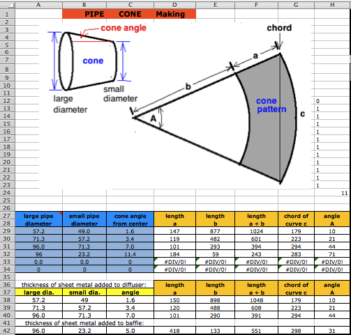 You can also use the Cone Layout software from this site which has the added advantage of making the cutout patterns for more complex designs. Questions & Answers What if the available space for the belly is less than the recommended belly diameter? Just make do with the available space. But the wider the belly the more power it will contribute. What if I design a pipe with a belly diameter greater than the recommended max? No problem but as you go much beyond it then you may need to use a decreasing angle baffle. What happens if my design varies from the suggested lengths on sheet 1? I encourage every one to experiment with variations from what is recommended to get the absolute best power. But usually what is recommended is very close to ideal. What if the recommended pipe section lengths on sheet 1 are impossible for the space available on my bike? Well then you'll have to change the lengths to match the bike. Bike designers have always had that problem. If the designed pipe is longer than the available space then consider changing the end of pipe powerband RPM so the design will be shorter or longer. On my bike I had to use a 2 cone diffuser design due to space limitations. Can I be lazy and just make the diffuser a single cone for my trail bike with reed valve? Yes but it won't have an ideal 'delayed' wave peak which is needed for optimal power for the trail. Maximum effort at making a great pipe is essential if you want the best power. Don't be lazy and take shortcuts. The enjoyment of the bike will far outlast these short lived difficulties. What recommendations can you give for designing a pipe for a bike for a beginning rider? For a beginner you might want a pipe that gives as little "hit" as possible. You can do that by making the belly width smaller, the belly longer, and the baffle longer. Also you can design for the end of the pipe powerband to be about 1000 RPM below the normal top RPM. It would make it more grunty like a trail bike. Also you can replace the base gasket with glue and add an extra head gasket, all to lower porting for less peak RPM. What can I do to get more pipe boost? If your pipe powerband is longer than what you want or need then you can shorten the baffle with steeper angles for a stronger but shorter return wave. Keep in mind that the wider the belly is, the stronger the cone angles will be for the same cone length. Bigger angles mean stronger return waves. |