|
When looking at the following graphs keep in mind that the higher the number of timing, the more advance there is because that is the number of degrees before piston top dead center (BTDC) at which the spark happens. Retarding the timing means lowering the number of degrees BTDC that the spark happens at. There are two on-board multi-switches on the circuit board. 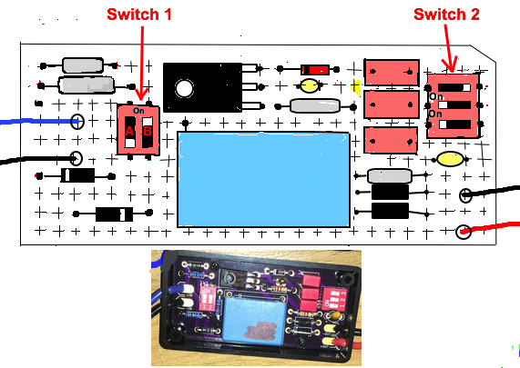 Switch 1 (SW1) is a dual switch that controls the whole ignition timing curve (to be more advanced or retarded/delayed) but affects the middle of the curve more than the end of it. Insuficient advance at mid range RPM limits the "grunt" of the engine. 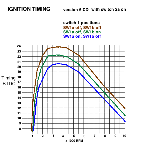 Switch 2 (SW2) is a triple switch that controls the amount of retard to the timing after 4500 RPM. So it has the most affect at high RPM. When high RPM timing is not retarded enough then that limits how high the engine can rev.  DETERMINING BEST SETTINGS: You can test the settings for your bike to see what works best. Jetting, porting, compression*, and exhaust pipe all affect the needed timing. Whichever settings allows the best power are the ones you should use. * high compression heads with squish bands (when the clearance to the piston is no more than .8mm) burn the mixture quicker and so needs retarded ignition via Switch 2Engine Oil and Ignition Timing My own testing proved that different types of engine oil affect the speed of combustion which affected the needed ignition timing. That combined with the strength of the voltage going to the CDI affects what setting you should consider "baseline" for switch 1. "Stronger magneto" refers to using either a stronger magnet, or a stronger stator coil that is fatter and without the 3rd wire for lighting. Click here for classification of many engine oils. 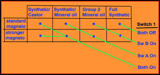 Fine Tuning First please buy a WalMart speedometer if you don't have one! The chart above will get you pretty close to perfect if the head is standard, or if you have an aftermarket head but the clearance between the squish band and the piston is more than 1mm. If the clearance is less than 1mm then you'll need to find the best setting of switch 2 for best top speed. If you doubt the chart suggestions then you can just try different positions for switch 1 for best speed going uphill. If you have an expansion chamber: Take it off and do the test procedure above with the stock pipe. Then put the expansion chamber on and retest speed. If slower then your header (straight pipe from engine to chamber) is too long. That header length determines the speed at which the expansion chamber limits speed. It has to be "tuned" for your ride. The shorter it is, the more the top speed. (but keep in mind that the stock low height of the exhaust port also limits top speed and it has to be raised at least 2mm for a significant improvement in speed. Raise the transfer ports 1mm for every 3mm change in exhaust port.) HOW TO UTILIZE THE SWITCHES: Just remove the boxes 4 screws (hidden under rubber feet) with a small Phillips screwdriver. Once the box lid is removed you can see the switches and easily change their lever positions using your fingernail or a small screwdriver. The on positions of Switch 1 are "up" and switch 2 on positions are "left" when the components board is positioned the same as in the drawing below. More resistance (selected by switch 1) causes more ignition advance. More capacitance (selected by switch 2) causes more top RPM ignition retard. Try to remember it this way when you're out testing: The more switch 1 is off, the more mid range timing is advanced which affects mid range power. And the more switch 2 is on, the more retarded the timing is (for high RPM) which affects power at high revs. |