| You can customize the top RPM and the powerband (RPM range of extra power from the pipe) by making a custom pipe or modifying the existing one. A good pipe calculator allows you to have that personal touch on your mini racer. 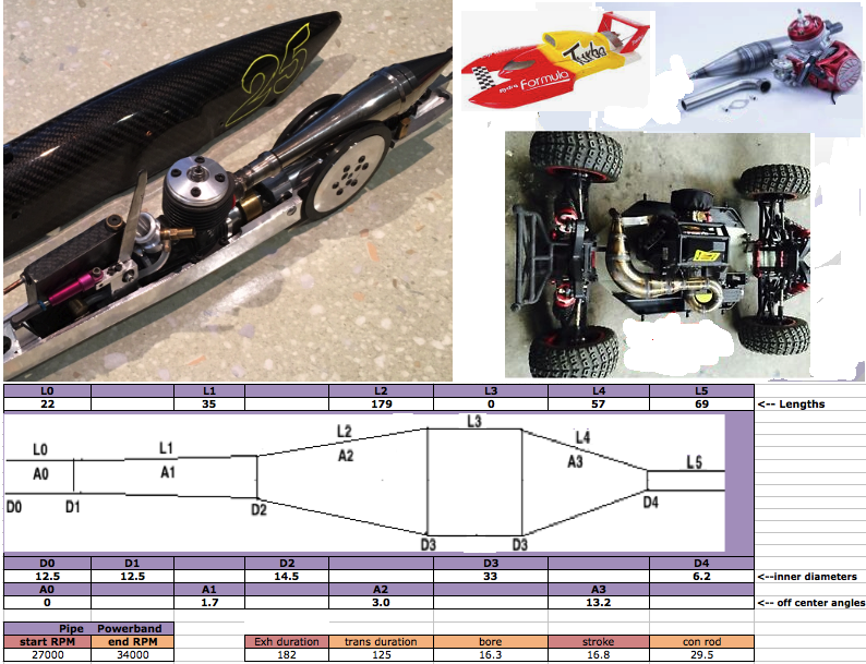 What is a "tuned pipe"? They are known by their expanding and contracting cones (diffuser and baffle cones), and their relatively short belly sections (which sometimes aren't even there). They have a shorter powerband but much better peak power. The powerband when the tuning of the pipe is aiding engine power is typically the upper 25% of the RPM range. Here's a dyno showing the horsepower gain from switching from a straight pipe with muffler (red graph) to a tuned pipe (black graph). Quite impressive, eh? This was from a moped. You can see the pipe powerband from 5000 to 7000. (28% powerband) 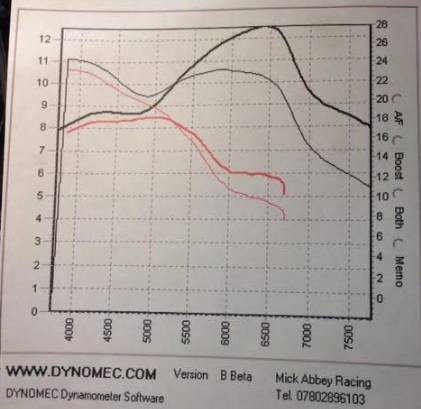  A less powerful response can be had over a much longer RPM range by having a really long belly ending abruptly or with a short cone. Some watercraft and trucks employ this method but this pipe calculator isn't equipped for that calculation. It only calculates for a tuned pipe.  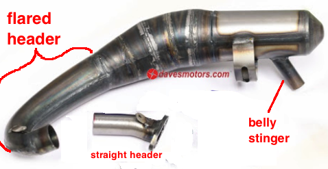 This Excel spreadsheet handles a top RPM from 16,000 to 48,000. You just enter the end RPM of the desired pipe powerband, % powerband desired, all the engine data, and the header and desired belly diameter and then click the calculate button and it will calculate all the pipe segment lengths which is most important to match the timing of the port openings at high RPM. The only tricky aspect is knowing the sound wave speed inside the pipe which is different for different fuels. The main variable that changes is the gas constant which is 277 for gasoline and 250 for fuel of 80% methane and 20% castor oil. The amount of castor/synthetic oil used changes the wave speed and this calculates those changes according to the % of oil used. The main variable to consider is the exhaust gas temperature which is hard to measure with these little pipes although the program is already set with the typical 500C at 36,000 RPM. But that can be changed in the program to suit your setup. Just figure out the top RPM of your engine and then enter all the pipe and engine details and then adjust the header temperature till the #'s at H2 and I15 are the same. Then you can proceed to design a new pipe using that temperature. About This Calculator: It is the result of years of usage of my own design of 2 stroke pipe calculator based on its own return wave simulator. This led me to be able to calculate the return wave lengths on sheet 1 without a return wave simulator and to know the typical positions of the waves in relation to the ports open/close timings at the RPM of the beginning and end of the pipe powerband. Of course it is more than something using a simple formula. This calculates the wave speeds, the return waves duration, the port timings, the recommended belly and stinger diameter, and the recommended pipe sections lengths. Click here for the usage instructions for a more in depth understanding of using it. A helpful video: Intro to using spreadsheets Download my free calculators spreadsheet to check your computers ability to use an Excel spreadsheet. Questions & Answers Am I confined to keep the same style of pipe that my engine came with? No, the different types of pipes can be interchanged. Why do some of the less race oriented engines come with the long belly pipe? The pipes with a long belly and abrupt end are for freedom from the 25% powerband of the typical expansion chamber. I had that design on my 100cc street bike which couldn't use an expansion chamber because the RPM spread between gears was too much due to the 4 speed gearbox. (5 gears is normal) It gave it a much more linear power response throughout the whole RPM range although its power peak was less. I know this because I made different pipes for it and learned a lot through the process. Is there any other disadvantage to the "normal " expansion chamber (short belly + two cones)? With the normal expansion chamber the return baffle wave causes a loss of power before getting up into the RPM range of the pipe powerband so for engines used thru a wide range of RPM often it is more advantageous to use the long belly design. Here's a power graph from a karting engine where you can see the dip from 7000 to 8250 RPM. The grey graph is from the baffle being perforated with holes to greatly diminish the return baffle wave which lessened its power peak but maintained an even power output for more RPM and got rid of that annoying power dip I'm talking about. Just design a normal expansion chamber, put lots of holes in the baffle cone, then weld an extension area around it to make sure all the exhaust still exits the stinger. 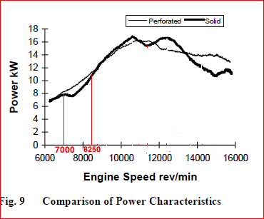 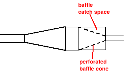 Is there any simple way to reduce the exhaust noise without reducing power? Yes, just make the stinger a bigger diameter and extend it into the pipe so that it starts at the beginning of the baffle cone. That reduces the noise 50% and has no loss in power. I make all my motorcycle pipes that way. I call it the "belly stinger". You can also just weld shut the stinger and drill a hole in the belly and weld a stinger pipe there.  How do you know so much about 2 stroke expansion chambers? About 13 years ago I got deeply involved in 2 stroke technology by studying and experimenting in order to improve my 55cc motorized bicycle. I tried using simple formulas and even bought the 2 Stroke Wizard and was dissatisfied with it all and so embarked on a 5 year journey of making my own expansion chamber calculator. Now I'm branching into the radio controlled market. Why should I buy this spreadsheet if I have no way to modify my pipe? Well, I believe where there is a will there is a way. But the biggest advantage with this program is to allow you to analyze different pipes to understand the details of what is happening with the powerband with each one. HOW TO BUY Just send $30 to a57ngel@yahoo.com by Paypal and the spreadsheet will be emailed to you. |