How A Two Stroke Expansion Chamber Worksby Michael Forrest 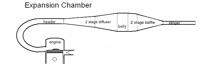 This site contains both well known pipe info and details never before discussed. Please don't dismiss this page as just another regurgitation of common knowledge. Near the end you will be presented with the latest and best software for design and analysis of 2 stroke pipes. I have made an Excel file for analyzing the dimensions of an expansion chamber to see if they are in harmony with the cylinder port timing and desired peak RPM of the engine. (An Excel file automatically does calculations and displays/graphs the results when information is entered into the correct data "boxes".) The Hidden Action of Expansion Chambers:  Wave
Speed Header
Diameter Header
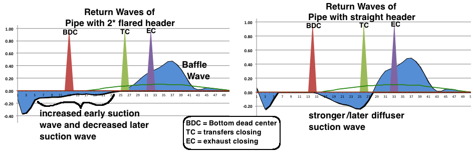
Length  Diffuser Angle(s) The two main considerations are: how many milliseconds long the return wave has, and what the shape of the diffuser is (whether it is a single cone or if multiple cones then what waveshape do they create so that it matches the type powerband you want). Greater angle of diffuser sections means the diffuser will be shorter. Jennings wrote in his Two Stroke Tuners Handbook that multi-coned diffusers cause a higher return wave peak which increases power. I would add that stronger return waves are more likely to suck out fresh intake charge from the cylinder unless the transfers have a good design so that they are good at directing the intake charge towards the back of the cylinder away from the exhaust port. Also a strong return wave may suck out too much intake charge if the front transfers are very close to the exhaust port. You can tell by looking at the pattern the intake flow leaves on top of the piston. (see example). The diffuser angles should also be in relation to crankcase compression ratio because a high ratio (1.5:1 or more) has more need of a strong vacuum wave from the diffuser to counter the crankcase suction as the piston rises after BDC. Otherwise some exhaust gas gets sucked back down into the crankcase. The advantage of a multi-coned diffuser: Since the main factor affecting the strength of the return wave is the percentage change of cross sectional area (every 10mm) then a single angle diffuser cone for my 55cc engine ended with a 6.5% area change (for the last 10mm distance of the cone) whereas a 3 stage cone I designed, although the belly cross sectional area was 9 times that of the header, ended up with a strong 9.1% area change at the end. A 2 or 3 stage diffuser causes the percentage area change to be more evenly spread out along the length of the diffuser instead of having very strong changes at the beginning (15.5%) and very weak changes at the end (6.5%). 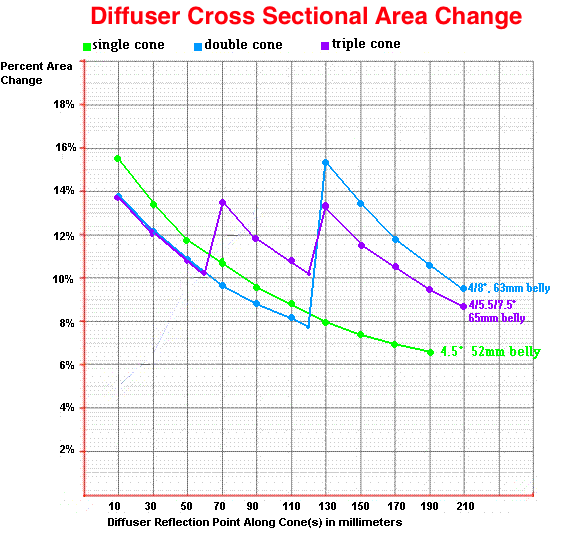 Here's the return waves for the 3 types of diffusers:  Click here to read more about diffuser cone angles. Maximum Cross Sectional Area of
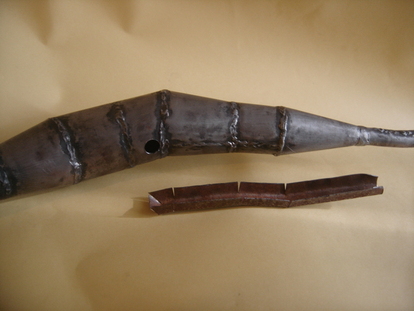
Diffuser The belly exists to keep the diffuser and baffle waves from overlapping too much which would cause a canceling of their pressure differences. You can see in the graph below (calculated using Boyles Law) that as the belly width increases there is a more minimal pressure change and therefore weaker return wave strength. 10 to 16 psi is a typical exhaust pressure peak in the header. The graph here shows the beginning absolute pressure of 25.5 (about 10psi). (The pipe functions with absolute pressures whereas we humans think in terms of relative pressures.) It is the pressure changes in the exhaust wave going thru the pipe that cause the secondary waves to return to the cylinder. The more pressure change, the stronger the return wave is. So although there are pressure changes all the way up to 4.5 times the header diameter it is just not recommended to expand that far because the % change per area change is just too small. My pipe calculator uses Boyles Law to determine the psi all along the pipe and the maximum belly diameter is determined by what will cause an absolute pressure of 4psi in the belly. So for peak exhaust header pressures of 10 to 16 psi that equates to 2.5 to 2.8 times the ideal header diameter. 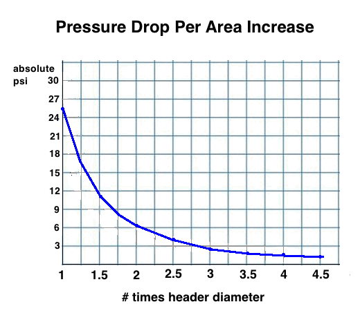 If the belly is too wide then that causes the end of the diffuser and the beginning of the baffle to be "dead zones" that cause very minimal return wave strength and so in essence lengthens the belly. That is why some people think that having a wide belly widens the powerband (at the expense of peak power). Well, it does but sometimes because it's causing a longer virtual belly section at the expense of the diffuser and baffle lengths which does widen the powerband at the expense of peak power. With most bikes there is limited space which sets the maximum diameter of the belly and so the diffuser and baffle have to be designed to accommodate the belly diameter. It is always parallel-walled. When designing a pipe it is always best to make variations to it and note the results at the power graph. Below are 3 graphs showing the difference in pipe powerbands for different belly lengths with a single cone baffle. The shortest belly gave the best peak power but the need for the powerband to be wider than each gears RPM range is more important than peak power. After you upshift you want to be within the pipe powerband.  The Baffle Cone The purpose of the baffle is to create a return wave so that at high RPM the return wave arrives back at the cylinder before the exhaust port is closing in order to increase cylinder pressure. Without it the piston will push intake charge out the exhaust port as it rises. Providing a pressure to match or exceed the pressure created in the cylinder by the ascending piston (~5psi) is the reason for the baffles return wave as well as increasing dynamic engine compression. Doing both things increases engine power at high RPM. Unfortunately, at all engine RPM except near peak RPM, the return wave returns when the transfers are open and tends to push exhaust gas and/or intake charge back down into the crankcase from the cylinder via the transfers which limits mid range engine power. But if you want an engine with explosive power on top then you have to have a strong baffle return wave. The baffle should be designed to match the bikes RPM range of the needed powerband which takes precedence over the peak power you want. A longer baffle due to a lesser angle will allow a slightly wider pipe powerband, but another advantage is less power loss when the engine RPM is just below the RPM range of the powerband. Tuned length The perfect location for the baffle, in distance from the piston, needs to be set to match the desired peak RPM of the desired powerband. The header, diffuser, and belly set its length from the piston. But if the baffle uses many cones of differing angles then using a formula can't accurately determine the tuned length because a formula doesn't take into account the modified baffle wave shape (due to multiple cones). Angle For a single angle baffle cone the steeper the angle the stronger the baffle return wave and the stronger the supercharging effect. Lesser angles cause less peak power but don't restrict pre-powerband power as much as a steep angle and so are better for trail bikes and street bikes (although you can eliminate most of that power dip with a boost bottle). Making a 3 cone baffle with increasing angles gives more power at the beginning of its pipe powerband. It is normally better for large bore engines or trail/street bikes. A 3 cone baffle with decreasing angles gives more power near the end of the pipe powerband. It is normally better for race engines. Click here to read more on this subject. Ratio of Diffuser Angle to Baffle Angle Others have written that the diffuser angle needs to be half that of the baffle angle but that is a crude generality that doesn't apply here because all the best of my pipe designs have multiple cones for diffuser and baffle which complicate the situation. All that really matters is the return waves and so I will speak in regards to them. If the diffuser wave peak strength is too weak in relation to the baffle wave peak strength then you will have that horrible pre-powerband engine drop in power that is common with race bikes (that are intended to only be ridden within their pipes powerband). I had a pipe do that on my 100cc street bike and it was completely annoying. It ruined my riding experience until I redesigned the pipe to not do that (by increasing the belly diameter and the diffuser angles). I wouldn't recommend allowing that to happen with any pipe design for an enduro or street bike. If your ride has that problem then you can also try lessening the pipe back pressure caused by the stinger (if it's smaller than what ECcalc recommends on sheet 1) by increasing the stinger diameter. Back pressure adds to the baffle wave and detracts from the diffuser wave strength which increases the pre-powerband power dip. Stinger/Silencer The stinger acts as a bleed off valve for the pipe. It controls the amount of average pressure in the pipe. So too narrow or too long a stinger will increase the back pressure and decrease the diffuser wave too much. The pipe pressure caused by the stinger increases with RPM so that the highest pressure is at top RPM which is why it hurts the diffuser wave the most there, more so than at mid RPM. I never believed that the length of a tube would have much affect on its ability to flow air through it till I blew into two tubes of the same diameter but different lengths and could feel the difference of resistance to flow between the two. Then I looked for a good flow calculator and found one that works good. We can use these input parameters: diameter stinger interior in inches (which is millimeters/25.4), GPM=(cc intake volume x 1.5 thermal expansion x .00027 conversion factor cc to gallons x RPM), length of stinger in feet (mm/305), .001 specific gravity, .34 cP viscosity for exhaust, results in a calculation of psi difference from beginning to end of pipe. Experimenting with stinger diameters and using the flow calculator I concluded that a good range of stingers would provide about .2 psi which my spreadsheet does a good job of calculating diameters and lengths to approximate that. If you want to double check the results of my pipe calculator just go to the flow calculator site. For more on stinger sizing click here. Flow restriction from the silencer, if not a completely flow-through design, contributes to total exhaust restriction and to back pressure which restricts the engine a bit. For example my Suzuki 100 gained 10kph more top speed when the silencer was removed. Excessive exhaust restriction also adds to engine heat. If the stinger originates at the side of the belly, and not the end of the baffle, then the exhaust pulse loses its bark and bite for a much more silent exhaust system (a whopping 84% quieter according to my decibel meter). Although my computer mic doesn't capture the sharpness of the exhaust note exiting a standard stinger, you can watch this video to see and hear how quieter the exhaust is when it exits the belly. Gordon Jennings wrote that a belly stinger adds a little bit of mid range power without losing any high RPM power. His belly stinger was the stinger pipe stuck up into the pipe so that its beginning was at the same distance from the piston that the beginning of the baffle was. Just be sure to weld a little support connecting the inner stinger to the belly so that it won't break its weld from being moved up/down by you hitting bumps at speed. Here is what he wrote on the subject:  Click here to see a belly stinger "channel" before being welded to my pipe. I cut off the previous stinger and had it welded to the belly stinger channel. Then the end of the baffle cone was welded shut. Click here to see the end product. The graph below shows how too much pipe back pressure can elevate the whole system of return waves. This is from one of Blairs research papers with a 172cc engine. Note also how the EGT at the belly changes with stinger differences. D3 is the stinger diameter in inches.  My experience tells me that if the intake of an engine is restricted with too small a carburetor or too small a reed valve then it's best to have a big diameter stinger for no back pressure. (Also a free flow silencer.) Click here to go to my page about carb sizing. Secondary Waves When the returning diffuser wave and baffle wave gets to the cylinder some of their energy is expended (if the exhaust port is open) and the rest bounces back into the exhaust pipe. Those sound waves return a second diffuser wave from the diffuser and a second baffle wave from the baffle. And then the process repeats over and over many times till all the waves energy is expended. All these waves following the primary diffuser and baffle waves I call "secondary waves" because they are of secondary importance to the primary diffuser and baffle wave. The secondary diffuser waves increase the primary diffuser wave and lower the primary baffle wave. The secondary baffle waves decrease the primary diffuser wave and increase the primary baffle wave. The graph below shows the waves occurence in relation to the timing of TC (transfers closing) and EC (exhaust closing) from 7500 RPM to 10500 RPM in milliseconds after exhaust opening. It's beneficial to pipe power to have positive pressure at EC and negative pressure at TC but the return wave at 7750 in this example is contrary to positive pressure at EC (see return waves graph below). The position of the secondary waves in relation to TC~EC depends on the header and diffuser length. The longer the header, the later those waves occur. So we can manipulate when they occur by either lengthening the header and shortening the diffuser, or shortening the header and lengthening the diffuser. You mostly have to accept when the secondary baffle waves occur because you have to change the pipes tuned length (and peak RPM) to change when they occur. 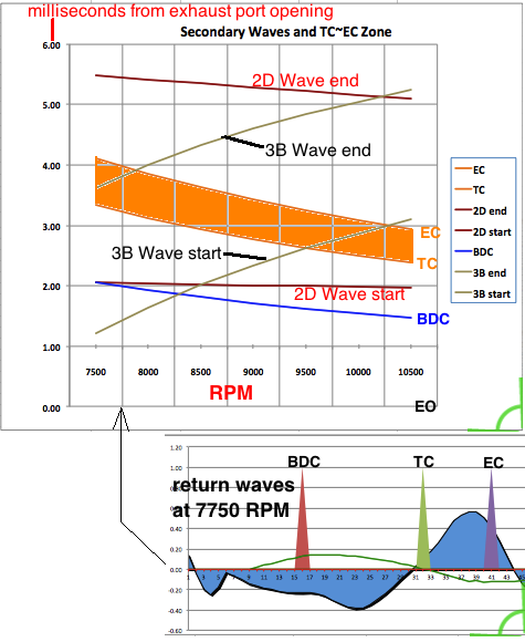 The latest version of my pipe calculator allows you to incorporates the seconday waves to the third generation with the primary waves which affects the pipe power and RPM range. This adds another degree of accuracy that the "plain" pipe calculators, that only depend on a few basic formulas, don't do. The complexity of calculating this accurately past the first two generations was too much for me so it only can incorporate those two generations of secondary waves. So you can change the header and diffuser length (keeping the distance to the belly the same) and see what results best when incorporating the secondary waves. My Expansion Chamber Calculator, how to obtain and use it. The mathematical basis for the calculations of the return waves in my Excel file. An example of pipe analysis and redesign. Pipes built using this method. My video showing how to make a pipe by hand. How ECcalc agrees with the real life exhaust pressure graphs from Blair. Four examples showing how accurate ECcalc is compared to dyno graphs. Pipe Design Questions & Answers Other pipe calculators available. Questions and comments can be directed
to me, Michael, at 19jaguar75@gmail.com
details from "Design
and Simulation of Two Stroke Engines" 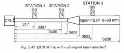 Here is the graph from page 181 showing the sensor #1 sensing the initial pressure wave, and then the negative (vacuum) return wave, then the return wave bounced back from the closed cylinder port, then the wave reflected back from the diffuser as a positive wave: 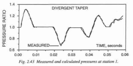 What is most important about this test is the recorded time it takes for the wave to travel these known distances. The distance, in meters divided by the wave speed, in meters per second (mps), gives the time of wave travel. (m/mps=time) This test proves that the negative return wave is reflected back all along the length of the walls of the diffuser cone. Doing a graphical analysis of the wave graph I determined the initial positive wave was 7.2 milliseconds wide and that the negative return wave was 8.8ms wide. The increase in width is due to the length of the diffuser, at the end of which is where the last of the positive wave reflects back from. The way to calculate the return timing and length of the negative wave in a 2 stroke expansion chamber is by this formula: WRT1=(D1x2)/SW where WRT1 is the wave return time for the first part of the wave, D1 is the distance from cylinder port to beginning of diffuser, and SW is the speed of the wave which is determined by the temperature and chemical composition of the exhaust gas (and almost impossible to calculate). To figure the return time for the end of the wave is WRT2=((D2x2)/SW)+WW/2 where D2 is the distance from port to the end of the diffuser, and WW is the width of the initial wave which is figured thusly: WW=(60/RPM)xBD/360 where RPM is the top engine rpm, and BD is the blowdown in degrees (exh ATDC - transfer ATDC). Baffle Cone and its Return Wave Next we can glean information from his test on the baffle cone: 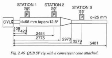 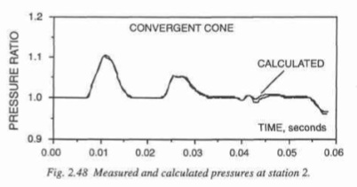 Doing a graphical analysis of the wave graph I determined the wave action can be determined in the same way as with the diffuser cone except that the return wave is positive instead of negative. The return wave starts its return at the beginning of the cone, and the end of it begins its return at the end of the cone. This effectively defines the return action of the wave in a very specific way, with no room for other theories. |