|
Two Stroke Expansion Chamber Design Professor Blair's tests proved that the
return waves timing can be calculated fairly closely using the straight
distances and the pressure wave speed in the pipe for that distance. He
also proved that the return waves are generated all along the length of
the diffuser and baffle cones. So I put formulas based on that in
an Excel workbook file to analyze an existing expansion chamber, or
help design
a new one, based on the
timing of the return waves in relation to the timing of the ports. I made my own return wave simulator to enhance this process. In 2016 I discovered Blairs research paper about his dyno and a karting engine where he gave full details, including exhaust gas temperatures and pipe return pressure waves graphs. I then fine tuned my formulas to match his results for the pressure waves and horsepower graph. It also agrees with different customers horsepower graphs.
The spreadsheet includes my equations for: 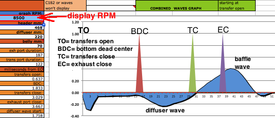 Out With the Old:
 ECcalc versions: I have been working on this for 5 years off and on, and previously I made the early versions available free of charge because essentially I considered them to only be "beta" versions, awaiting the final product. My latest are versions 28 and 30, and they work as good or better than any of the expensive pipe design programs you can buy, but they are easier to use. Get them now and make yourself an excellent pipe! Both versions are included when you buy ECcalc. No-charge assistance is part of the package also. Just fill in the spreadsheet and then send it to me to check for errors. ECcalc28: It's a little less accurate but it's not limited to a piston stroke of 27mm - 86mm like versions 30 is. It can use longer and shorter strokes. It also doesn't calculate for flared headers ike version 30 does. Click here for the website usage instructions. ECcalc30: This will calculate a pipe with a straight or flared header and then let you adjust all dimensions for more RPM range or more power (not both). It lets you enter the measured widths of the exhaust port or let the program estimate the widths based on what style port it is. Final power graph is based on its return wave simulator. Click here for the website usage instructions. The usage instructions videos and other instructional videos on YouTube are here : videos page ECcalc-hiRPM: Since 28 and 30 aren't for engines reving higher than 15,000 RPM I've developed a version for high RPM engines calibrated with the specs from the world champion mini race car. Click here for more info. My pipe building resources page The mathematical basis for the calculations of the return waves in ECcalc. An example of pipe analysis and redesign. Pipes built using this method. My video showing how to make a pipe by hand. How ECcalc agrees with the real life exhaust pressure graphs from Blair. Four examples showing how accurate ECcalc is compared to dyno graphs. Pipe Design Questions & Answers Buy ECcalc via PayPal by clicking hereECcalc Features 1. Limitations: Acceptable piston stroke is 28mm to 81mm in version 30. In version 28 there is no such limitation. Minimum to maximum acceptable exhaust pulse widths are .45 to 2.1 milliseconds in version 30. Click here to download a spreadsheet that will let you figure out your engines exhaust pulse time duration. For engines with ignition timing that doesn't vary with RPM I have made a new option for them but it requires the user to measure the exhaust gas temperatures. 2. This Excel spreadsheet uses sophisticated mathematical means to determine the return waves shape, length, and peak which are used in additional formulas to determine the extra engine power the expansion chamber is contributing to the engine throughout its RPM range. 3. With input of manually measured exhaust area it calculates the exhaust pulse time which determines the time duration of the return waves. 4. The exhaust pulse time changes with RPM. Past ECcalc versions didn't vary it with RPM. 5. Sheet 1 allows the user to find the basic pipe dimensions that harmonize with the engine port durations and RPM and then allow the user to fine tune them on sheet 3 in a way that no formula based calculator can do. 6. It uses formulas for determining the different wave speeds inside the pipe based on different exhaust gas temperatures determined by heat loss from the pipe walls according to the diameters and lengths. The method was calibrated by the data of end pipe temperatures listed in one of Blairs research papers. 7. It has an accurate method of calculating the return wave strength and form by using Boyles Law which teaches that as the diameter increases, the psi change decreases. Since the return wave is generated by the psi changes then this non-linear way of calculating is the only valid way. 8. It shows a simple way to create the "flat sheet" patterns needed to cut out the right pattern of sheet metal needed to make each cone. No computer program is needed, just a long metric ruler, poster paper, an ink pen, and a Marks-A-Lot. Getting a Pipe Designed: Email me at a57ngel@yahoo.com if you want me to do it for you. Cost is $75 via Paypal. Go here for details needed. Here's a testimony from a happy user of ECcalc: "I didn't like Bimotions pipe design software so I bought and used yours. I like the fact that I can see what pressure/vacuum is present in the port at the different piston/port positions. This 1973 Yamaha MX 250 has got 225 psi cranking compression. A little high, but it pulls hard and starts easily. The owner can't believe it starts on the first kick, and idles well while people around him are blipping the throttle in the staging lanes to keep their bikes running. On top of that he always gets the hole shot to the first turn, even against 500cc bikes in other classes. At the pacific northwest AHRMA award ceremonies the picture they put on all of the plaques is the Yamaha leading a couple of other bikes into the first turn. Pretty cool! The bike does epitomize the intent of the class with its old fashioned expansion chamber instead of a modern snail pipe, and looks pretty much stock on the outside. At one point I attempted to raise the RPM's a little by shortening the header pipe 25mm. I don't know what you use as a temp probe. I was using some assumptions when I designed the pipe as the motor was not running yet. So I put the top of a Fluke immersion probe into the pipe as I went for a ride. It seemed really low like 375*C so I did not trust the readings. I went ahead and shortened the pipe anyway. It actually seemed worse on the top end. I decided to run ECcalc with the lower temp #'s and everything matched up with what I was feeling. So, I retarded the fixed ignition timing like .010" to put some more heat into the exhaust. OMG the shortened pipe with less timing really came alive, more mid-range and more RPM's. In fact at the next race he started having clutch slippage in higher gears. It has new Barnett frictions and steels. So, I just installed heavier springs, and a new clutch cover as there was some hairline cracks in it. I am thinking I should lower the compression down a little so it won't retain as much heat in the motor and maybe make more power at the end of the race, I don't know. It works pretty damn good, I hate to mess it up." |