|
Making an Expansion Chamber
How to design an expansion chamber using my system:
First read my explanation of exactly how an
expansion chamber works
if you have not already. This first example
is for a 125cc engine peaking at 8000 rpm that needs a powerband like an enduro woods bike
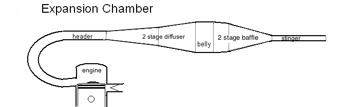
(between MX and street). We will make it with a three stage diffuser and
a single
stage baffle cone. Multi-stage diffusers broaden the powerband a lot
but lower the peak power just a little. Multi-stage baffles increase the
return wave time from beginning to peak which is helpful for engines peaking at less than 7000 rpm.
 Determine header diameter: Determine header diameter:
If you don´t want to keep the original pipes header and want to make
your own then use this formula: Header diameter = 2 x sqr root
of ((.00085 x cc x rpm)/3.14) which gives 32.9mm for a 125cc engine peaking at 8000rpm. For an expanding header that would be the beginning diameter of it.
Determine header length:
Engine porting is at 179° exhaust duration and 123°
transfer duration and the top rpm is 8,000.
(You can select the desired top rpm and design for it or put a header/muffler on the engine and see how fast it goes then use the mph and the gear/sprocket teeth to determine rpm if you don't have a tachometer, then add 10% to that for a peak rpm.) Let's say we use a mid header temperature of 660° Celsius (see notes on measuring at bottom of page) which means the header needs to be 470mm long (distance from piston to beginning of pipe) for the "return
time of start of diffuser" to match the BDC timing of 1.86ms.
Determine the diffuser length:
With a 470mm header the diffuser needs to be 210mm long for the "end of
diffuser wave" to match the transfer closing time plus .15ms. Letting the
baffle return wave overlap will shorten the end of the diffuser return wave so the zero crossover point can occur just after the timing for transfer closing. (Around .025ms after TC is perfect).
Determine the diffuser sections:
Trying different angles I could see that with a maximum belly diameter I got too strong a return wave peak (.22 using sheet 3 of the Excel file). So I made the belly 90% of the maximum to lessen the diffuser angles. That worked good. Now wanting around 73mm as the belly diameter I made the three angles 3.5, 6.5, and
11.5 degrees at 80mm, 60mm, and 40mm lengths which gives 72.7mm belly diameter. Flaring the header pipe is another trick available to lessen the diffuser angles but it complicates the construction of it and a flared header is not needed for engines peaking at less than 10,000rpm.
Diameter of belly:
I
think it was Blair that said the belly diameter shouldn't result in more than
6.2 times the area of the beginning of the header. But the area
available on the bike and/or the desired diffuser angles is usually the
determining factor. When desiring maximum torque from an engine you want to design for a fat pipe since fatter bellies allow for larger diffuser angles and longer baffles (for a wider powerband).
Determine the belly length:
Use my Excel file to see if the "zero crossover" timing matches
the timing of transfers closing plus .025ms at peak rpm. Change the belly length to
match if it don't. With a 210mm diffuser length I had to make the
belly length 70mm in order for the zero crossover timing to match transfer closing plus .025ms. Sheet 3 gives the most accurate calculations and should be the final word in this matter. Sheet 1 gives rough estimates and should just be the starting point of design. Below is what the combined graph on Sheet 3 should look like. (The double hump of the baffle wave is due to using a baffle extension).

Designing the baffle cone:
For
a single stage baffle around .7 is a good return wave peak strength if you want
decent but not extreme top rpm power. Using the Excel file enter 72.7mm in the "belly diameter" space. Trying different
numbers in the box for "1st cone angle" I come up with 8.3 degrees as
that which
gives percent reductions which results in a wave peak of .69 using sheet 3 of the Excel file. You can see that the diameter at 100mm length is 43.5mm which
should be entered in the space for the "2nd cone beginning diameter". Enter 8.3 degrees into the "2nd cone angle" space. The Excel file shows
that to end up with a stinger diameter of 19.7mm (see below) the baffle
length would be 181mm.
Baffle design in relation to cylinder compression:
Jennings wrote, in his paper about the Hodaka hop-up,
that "it may be necessary to use a relatively ineffective expansion
chamber in cases where an especially broad power range is desired. This
will permit a higher compression ratio - which improves torque over all
engine speeds - without incurring any difficulties in carburetion." So,
unless you want the engine to be super picky about perfect jetting it
is best not to have high cylinder compression (above 150psi) with an MX
pipe. But it is OK to have higher than 150psi with an enduro pipe with
less baffle return wave pressure which we have in this case.
Stinger design:
58% to 60% of the ideal header diameter gives a good diameter for an enduro
pipe. 62% is better for a motocross or GP pipe. So .60 x 32.9 = 19.7mm. 12 times that distance gives 237mm (9.7
inches) as the stinger length but a bit longer or shorter will make no
noticeable difference.
*Measuring exhaust temperature: You might guesstimate the temperature but to be accurate you need to measure the mid-header gas temperature in Celsius with a thermocouple and gauge (source) while riding at top rpm on a flat surface. Only a real life test in conditions similar to use will give the right temperature since with clutch pulled in my other engine/pipe read 290 Celsius, and with clutch dragging in-gear it read 590 Celsius, but while riding it read 660. Lazy persons way to do this is just use 650 and build the pipe so different header lengths can be tested to see what gives the best top speed. If you measure the temperature in a pipe that's on a bike and you plan on making the stinger a larger diameter then expect the new pipe temperature to be less. Less pressure inside the pipe lowers temperature. I used to think that I could put just a header and diffuser on the engine (with no baffle) and test for correct header length till I found it. But now I know that having an open pipe lowers the temperature around 200 degrees which throws all the measurements off between such a test setup and the final pipe.
HOME
|