Single Cylinder Crank Balance Calculator
Some people will tell you it is impossible to balance the 2 stroke engine for little vibration but I’ve done it successfully and so have others. Most engines are fairly well balanced until the owner installs a non-standard piston or changes the compression ratio or rod length. What is “a little vibration”? It’s little enough that you can see what’s behind you in your handlebar-mounted rear view mirror because it’s not shaking. It’s also little enough that your hands and forearms don’t get fatigued just from the vibration.
In one DirtRider magazine issue Rick Johnson was talking about his 1986 works CR250. He said: ”For example, the magic Honda always had was the cranks. There was something about those cranks- I can’t tell you what they did to them but when you got on and rode there was virtually no vibration to your hands." This proves that an excellent balance can be had for 250cc and smaller engines. The higher you go over 250cc the more vibration you get although the crank may have the best balance possible.
A little vibration will always remain but if it is enough to bother you and you’re looking for ways to reduce the vibration at the bars then your engine needs some help. My ’89 KDX200 vibrated too much and fatigued my hands on long rides. I wish I still had it so I could balance the crank now that I know how. Click here for a simple way to test your crank balance.
There are 4 “vertical” up/down forces in-line with the cylinder. They are:
1) upper assembly (piston assembly, wrist pin, conrod around the upper bearing) inertia
2) the centrifugal force of the heavier section of the crank wheels (opposite the balancing holes) counter-balances the upper assembly the closer it is to TDC and BDC. (subtracting from it is the centrifugal force of the conrod big end, the bearing, and the rod pin minus the lack of force from the rod pin holes in the crank wheels).
3) The connecting rod contributes to the value of the upward and downward force of the piston assembly.
4) The compression/combustion force also contributes.
The 2 "horizontal" (forward/rearward) forces are:
1) the balance holes in the crank wheels offset the up/down piston assembly force but since there is nothing to counter balance it in the horizontal plane it can make vibrations if it's too much.
2) the connecting rod contributes around 5% of the value of the centrifugal force of the crank wheels to the horizontal.
The piston assembly force is more around TDC because piston inertia is more there than around BDC due to the geometry created by the crank and connecting rod which causes maximum piston speed around 78 degrees before and after TDC. The upper piston assembly (piston, rings, end of con-rod, wrist pin, bearing) should be as light as possible because the unbalanced weight of the crank wheels can somewhat counter the forces in-line with the single cylinder but then create a fore/aft vibration due to lack of piston movement in that plane. If I’m analyzing an engine and I find that it needs a lighter piston assembly then I look at the wrist pin to see if it’s hefty enough to be able to drill out a larger diameter hole in it without causing it to be too weak for the engine. That lightens it up. Otherwise it’s just a matter of selecting the lightest aftermarket or OEM piston (such as Athena). If that’s not enough then the crank has to come out so balance holes can be drilled in it close to the connecting rod pin.
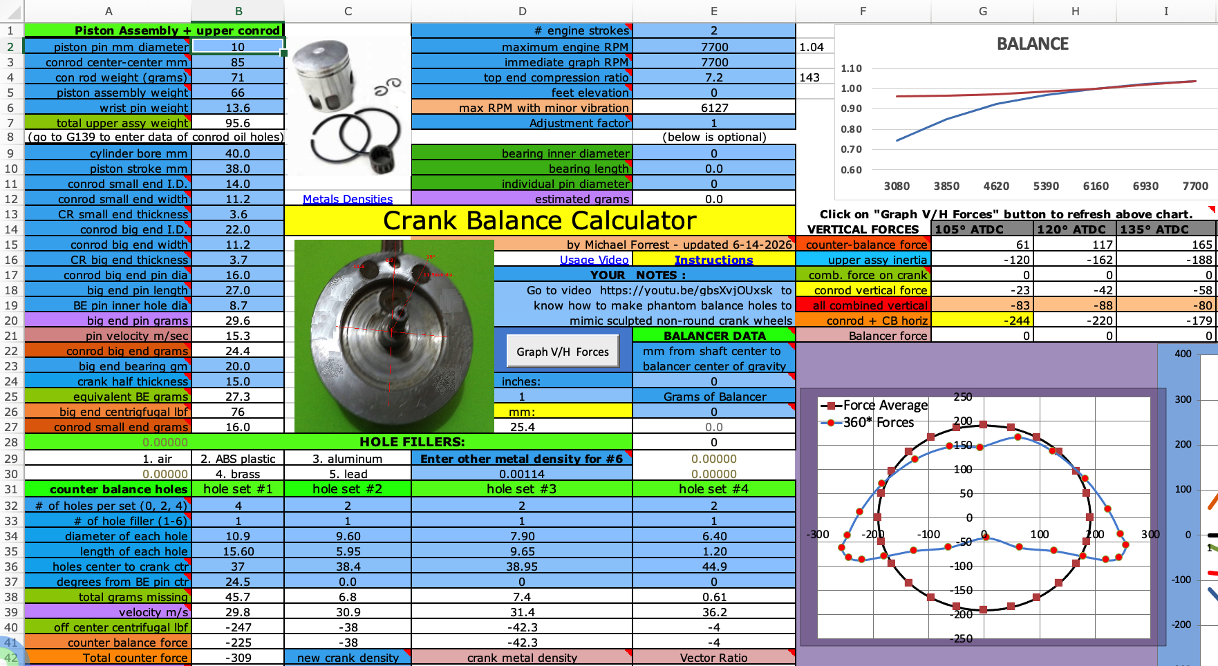
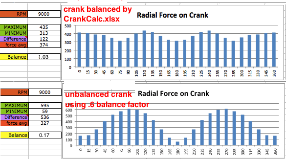
I have made my own software that displays a graph of the vertical and horizontal forces and their combined result as radial forces throughout the 360 degrees of crank rotation. The goal is to counter-balance so the vibrational forces are as minimal as possible at peak RPM. The better the balance, the less rider fatigue which means more time of riding pleasure. My 55cc engine vibrated like crazy, and after drilling just two 9mm diameter holes in the crank wheels it was like normal.
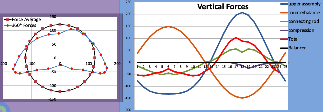
To use my crank balance calculator just enter in all the required data into the light blue boxes and then click the "Graph V/H Forces" button. The closer to perfect the balance is the smoother the ride will be and the less stress there will be on the crank bearings. Also less nuts and bolts will work themselves lose. Here are the graphs illustrating what good balance is:

The green graph (lopsided) on the left shows the radial forces on the crank through 360 degrees of crank rotation. The reference zero point is where the x and y scales cross. The black graph is the average. The right graph shows the different vertical forces on the crank thru 360 degrees. The red graph is the sum of them all with the right half around TDC and the left half around BDC.
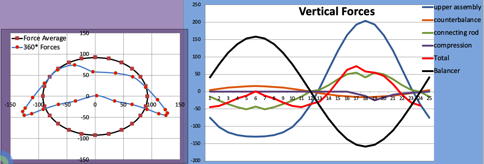
Below are the same graphs when an extra balancer shaft is part of the design. The black graph on the right is of the balancer force. Unforunately I haven't verified that my computations for this setup align with reality.
The best drill bits to use are carbide or cobalt. Here are some soures:
Grainger carbide drill bits, cobalt drill bits
(use 5/32” to make pilot hole then make the final hole.)
McMaster-Carr has many carbide drill bits of high quality and can be used without a pilot hole.
My YouTube videos about crank balance: #1 #2 #3 #4
The last video explains how to figure out the equivalent balance holes
for a crank with sculpted out areas instead of balance holes.
Questions and Answers
Does this work equally for 2 strokes and 4 strokes? Yes. When you enter "4" at E1 for a 4 stroke the program halfs the combustion force since the exhaust/intake stroke is without such force. Halving it is making it average out correctly for 4 strokes. Other than that everything is the same for 2 strokes and 4 strokes.
Can this calculator be used for a crank that relies on true weights opposite the conrod pin? Yes it can. Just calculate with two counter balance holes with zero degree offset and when you have the final result for their right size then make the counter balance weights the same size as the imaginary holes.
Can this calculator be used for a crank that has some of its area sculpted out (not via drilled holes)? Yes, just look at the video describing the process: [video]
Are there any other programs available to do this? At this site is one available for $290 but I don't think it incorporates the combustion force. And I think they use the shitty old fashioned method of adding 60% of the con rod weight to the piston and 40% to the crank wheels. I think my program is the only one that painstakingly calculates correctly the con rod forces that are a significant contributor to the forces.
Why do big bore engines vibrate more? Because the larger piston and conrod are heavier. The heavier they are, the more imperfect even the best balance becomes. But anything smaller than a 300cc engine should not make so much vibration that it tires out your hands. If you use the lead pellet trick instead of correcting faulty counterbalance then you are leaving the crankshaft bearings to be victimized by the extra radial forces on the shaft.
Since the combustion force doesn't peak at TDC shouldn't the balance holes be a bit off center to compensate?
Yes but I experimented with doing that and the result was just a very tiny bit of improvement, not really worth the extra effort.
How does it calculate the balance? It calculates the horizontal and vertical crank forces for every 15 degrees of crank rotation. It then divides the graphs vertical force average by the horizontal/BDC force average and then multiplies that by the ratio of average radial force (comparing it to the average radial force that exists at the 1.0 point). The 1.0 point is where the vertical force is even with the horizontal/BDC force. This is a genius program, as are most of my programs, and should be treated with respect although the price is low.
Why is it so cheap? Although I have spent probably close to 100 hours developing it over 2 years I would rather many people have it than just a few. Unfortunately many people judge a product based on its price. Well if they knew me personally they would know I am off the beaten path and don't do things "normally" and so neither I or any of my products should be judged in a normal way.
Here's a testimony from a satisfied user:
" I have spent heaps of cash buying "balanced" cranks and "balanced bottom ends" [for a 69cc motorized bicycle engine]. Not cheap when shipped from the USA to Australia. I had two identical "jack-hammer" cranks and then bought this balance calculator. A GREAT investment. I did not trust estimating the con-rod weight, or the big-end or small-end sections of the con-rod for REAL accuracy. I stripped the crank to get EXACT measurements and weights. I cut off the big-end and small end (from a discarded conrod) to weigh them individually. The calculator is GREAT. You need to check your input figures and re-check them. Do not rush it. I found the experience very "addictive" and enjoyable. The crank when drilled with the calculated counterbalance holes has been proven to be my BEST CRANK. Jim Baker of OZ Motorised Bikes; a no bullshit facebook Group; where you find my posts about this."
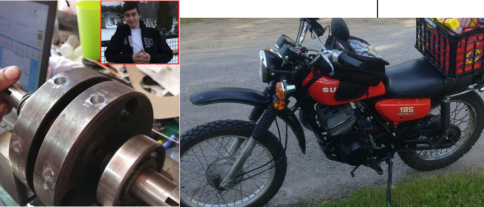
Louis replaced his stock Suzuki TC185 piston with one 50gm heavier and used this program to know what size balance holes to drill into the crank. He wrote: "thanks for your crank balancing spreadsheet, I balanced my crank and it made the engine soo smooth". He used a drill press and a drill stop to ensure perfect holes. The engine was vibrating real bad with the heavier piston before.
If you have an unanswered question then please shoot it to me at 19jaguar75@gmail.com
All the spreadsheets hidden comments are listed below for you in case your computer doesn't let you fully see them.
Sheet Cell Comment
Sheet1 $D$1 Enter 2 for 2 stroke or 4 for 4 stroke
Sheet1 $A$2 wrist pin diameter
Sheet1 $A$3 con rod length from hole center to hole center
Sheet1 $D$3 Set it to any RPM you want to see how the 360 degree graph looks like and see what the vector ratio is at E43.
Sheet1 $AT$3 crank rotations per second
Sheet1 $A$4 naked- without bearings
Sheet1 $D$4 compression ratio of trapped volume above exhaust port.
Sheet1 $F$4 cc area of piston top
Sheet1 $A$5 including rings + bearing but without wrist pin
Sheet1 $D$5 Riding area elevation which is used in the formula for cranking PSI.
Sheet1 $E$6 cranking PSI when rings are good.
Sheet1 $P$6 difference between the highest and lowest force
Sheet1 $A$7 piston assembly, wrist pin, con rod end (B27)
Sheet1 $D$9 bearing length in millimeters which is close to the width of the conrod section.
Sheet1 $D$10 up to 125cc is usually 2-3mm, 250cc is 3.5mm, 500cc is 4mm
Sheet1 $A$11 con rod small end race inner diameter
Sheet1 $A$12 side to side width of section that encompasses bearing
Sheet1 $A$13 thickness of con rod metal that encompasses bearing
Sheet1 $AK$13 This lowers the combustions downward force on the frame because most of the force is translated to rotary momentum in the crank wheels
Sheet1 $A$14 inner diameter of hole at large bearing end
Sheet1 $A$15 side to side width of section that encompassses bearing. Add in the thrust washers if there are any
Sheet1 $E$15 email: a57ngel@yahoo.com
Sheet1 $F$15 Conrod big end force minus counter balance holes force.
Sheet1 $A$16 thickness of con rod metal that encompasses bearing
Sheet1 $A$17 outer diameter of pin
Sheet1 $E$17 Updated June 13 2018 to include combustion force. Updated Jan 8 2021 to allow a different crank metal density at C43. Updated formula at E155 on Jan 14. Corrected balancer shaft calculation May 24 2021. Revised main formula March 2025.
Sheet1 $F$17 combustion force on crank center that contributes to vibration
Sheet1 $A$18 length of large con rod pin
Sheet1 $A$19 Big end pin hole diameter. This refers to the pins center hole which is necessary to lighten it up.
Sheet1 $E$21 This is for the data of an extra balancer shaft rotating opposite the crank. Its weight is downward when piston is at TDC.
Sheet1 $A$22 estimated grams of section that encompasses bearing
Sheet1 $E$22 See calculator at bottom of this sheet.
Sheet1 $A$23 Use the calculator at E8-10 if you can't measure its weight
Sheet1 $A$24 one crank wheel only, at big end pin
Sheet1 $E$24 Distance from center of gravity of balancer to center of its shaft.
Sheet1 $A$25 the net weight at the con rod pin area including the end of the con rod that encompasses bearing
Sheet1 $A$26 centrifugal pound force due to grams at B25
Sheet1 $E$26 Weight in grams of balancer without end shafts.
Sheet1 $A$27 estimated weight of section encompassing bearing
Sheet1 $D$29 Click onto D12 for the web site with densities for all metals and then multiply by .001 before entering it at D30. (Just move the decimal point three places to the left.) This is for if you want to fill a hole with anything other than air, plastic, aluminum, brass, or lead. For instance magnesium is listed as 1.7 but you should enter .0017
Sheet1 $A$32 0 cancels out all data below it in that column. 2 is only for when the hole is in alignment with the conrod pin, either 0 degrees or 180 degrees (on the opposite side). 4 is the typical setup of 2 holes for each crank wheel that are equal to each other in distance from the crank center and degrees from the conrod pin and diameter and depth.
Sheet1 $A$33 Refer to A29 to D30
Sheet1 $A$36 distance from center of hole to center of crankshaft
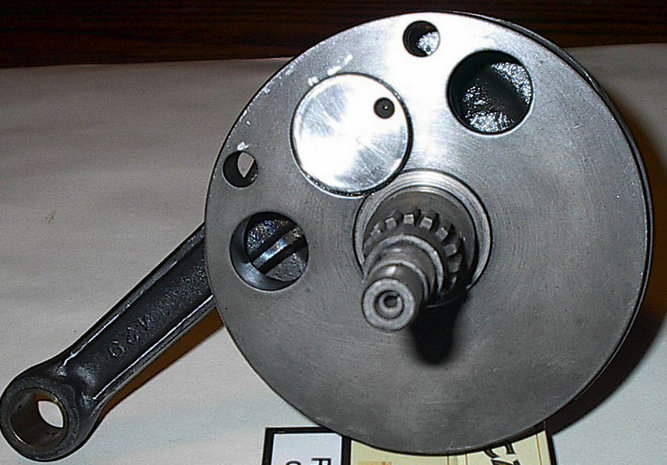
Sheet1 $A$37 In the example picture the big holes are 25 degrees off from the pin. 0 is aligned with the big end pin, and 180 is at the opposite location. You can put holes at 180 when the balance holes are too big.
Sheet1 $A$38 for both halves
Sheet1 $A$39 meters per second velocity
Sheet1 $C$42 Enter a different crank metal density if .00785 (for iron) isn't correct.
Sheet1 $D$42 This is the density the program will use if you don't enter something different at C43.
Sheet1 $E$42 Ratio of radial forces of the top 60 degrees of crank rotation to the second set of 60* from 105 to 175 degrees.
Sheet1 $A$43 weight hanging from con rod to keep the crank from turning
Sheet1 $A$45 This is just here to show you that balance factor changes greatly with each engine and is not to be considered a method for crank balancing since picking the right factor is just a guessing game.
Sheet1 $E$45 This will be 1.0 at the smoothest RPM. See the top V/H graph to see where it crosses the 1.0 line. See note at D46 also.
Sheet1 $A$46 Static balance weight divided by piston assy + pin weight with conrod small end weight
Sheet1 $C$46 The engine feels the smoothest from 1.02 to 0.99. You can set the "smooth zone" to be at a lower RPM range by changing the top RPM at E2 to be the end RPM of your "smooth zone", whatever that may be. You can set it to be the RPM range that you most often ride in. If the graph never gets below 0.99 then the balance holes are too big and you either need a heavier piston assembly or new holes 180 degrees from the conrod pin.
Sheet1 $L$46 average from 60BTDC to 60ATDC
Sheet1 $N$46 average from 135ATDC to 135BTDC
Sheet1 $A$53 angle from vertical
Sheet1 $A$54 from the center of its arc if continued to make a circle
Sheet1 $A$59 upward centrifugal force at TDC
Sheet1 $A$64 the center of its arc if continued to make a circle
Sheet1 $A$69 upward centrifugal force at TDC
Sheet1 $A$74 the center of its arc if continued to make a circle
Sheet1 $A$79 upward centrifugal force at TDC
Sheet1 $A$84 the center of its arc if continued to make a circle
Sheet1 $A$89 upward centrifugal force at TDC
Sheet1 $A$97 the center of its arc if continued to make a circle
Sheet1 $A$102 upward centrifugal force at TDC
Sheet1 $A$107 the center of its arc if continued to make a circle
Sheet1 $A$112 upward centrifugal force at TDC
Sheet1 $A$117 the center of its arc if continued to make a circle
Sheet1 $A$122 upward centrifugal force at TDC
Sheet1 $A$127 the center of its arc if continued to make a circle
Sheet1 $A$132 upward centrifugal force at TDC
Sheet1 $F$135 total vertical force
Sheet1 $G$144 This calculation will be used in the calculation at B27.
Sheet1 $G$149 This calculation will be used in the calculation at B22.
Sheet1 $E$150 Weight after subtracting the grams of the end shafts
Sheet1 $E$153 Enter this value at E36
Sheet1 $E$158 The diameter in millimeters.
Sheet1 $E$160 The height change of the water in millimeters.
Sheet1 $E$162 This assumes the main metal is iron.
214,664 starting Jan 29 2017