| Steps: First just enter the needle ID, main jet #,and C28 (slide open mm # taper start). Nothing more. 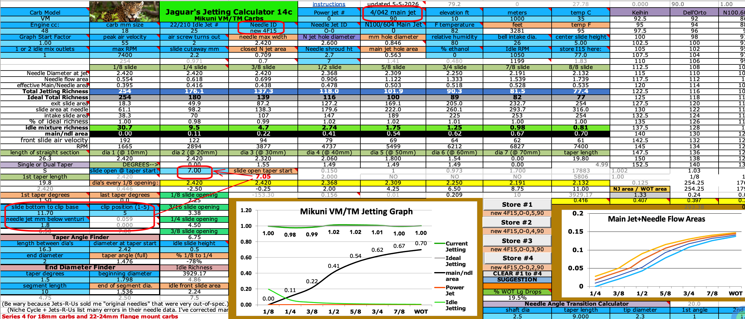 Making it Richer Mid Throttle You can take note of the 1/2 slide number on the main graph (.41 in this example), then find a needle that bends the graph more with more taper angle to increase that number. Without changing the needle all you can do is screw up the low throttle jetting by changing C28 to be more mm or less mm. If you order another needle you can change the clip position because mid throttle jetting is more important than low throttle jetting. Different Needles On my spreadsheets Mikuni VM sheet it lists available needles. The #4 series are mostly of the correct length for my Mikuni VM18. The bigger the taper angle(s), the richer the jetting will be mid throttle. The 4F15 I am using with its 1.5 degree taper is just right but if I needed it richer then I would try the 4J11 needle with its 2.5 degree taper. Be aware that the steeper the angle the more easy the flow of gas is at WOT and so the smaller the main jet needs to be. If your current setup is good at WOT then write down the # at I14 and then with a differnt needle ID entered at D5 then keep changing the main jet # till I14 returns to the number it was before. 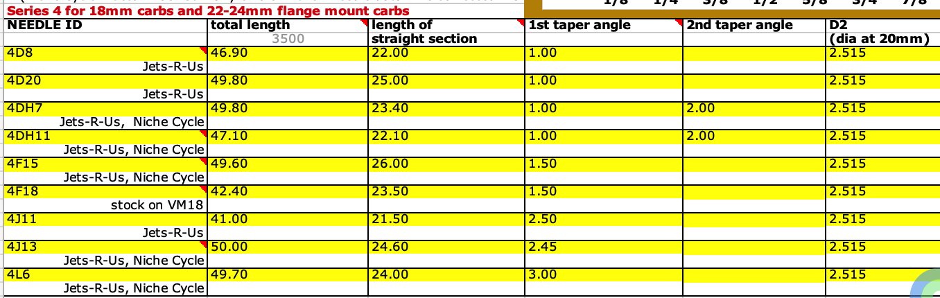 Multi-tapered Needles I generally prefer single tapered needles but sometimes a dual tapered needle allows you to raise the needle more for more richness down low. Clip Position For most bikes the correct clip position causes the taper to "kick in" at any where from 1/4 slide open to 3/8 slide open. By that I mean that the beginning of the taper just starts to come out of the skinny part of the needle jet at those slide openings. (Note I rarely say "throttle position" because closed throttle isn't closed slide, and can vary a lot.) The clip positions are numbered 1 to 5 with 1 at the top and #5 being the lowest. Length of Straight Section That distance works along with clip position. For example the 4F15 in my VM18 is set to the 5th clip position which pulls the needle up the maximum. I could pull it up more with a home-made washer under the needle clip if I wanted to, but I don't need to. So this needle has a 26mm length but since it likes the 5th position that means I can use any other needle that is any where from 26mm to 21mm (because 26 - 5 is 21). All of the #4 needles are within that range. If I used the 4J11 at 21.5mm length then I'd need a 0.5mm washer under the clip set at the top #1 position. (26 - 21.5 = 4.5) Needle Diameter With Mikuni VM's the diameters are uniform but you can change the needle jet for different inner diameters which changes the flow area around the needle at closed throttle. This area affects the low throttle jetting. Old bikes have their needle jets wallowed out which allows too much flow and so causes low throttle jetting to be too rich. The larger the engine the less years that jet lasts due to more vibration. Keihin carbs have set diameter needle jets and so you can only try different diameter needles. Dellorto offers different diameter needles and different diameter needle jets.
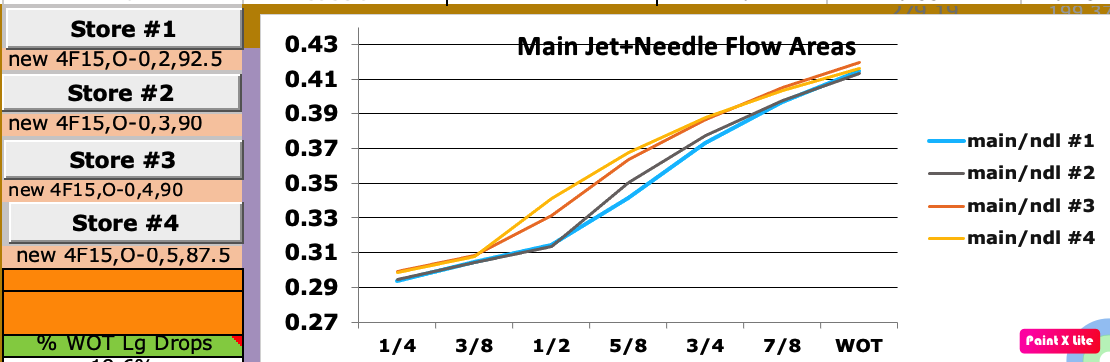
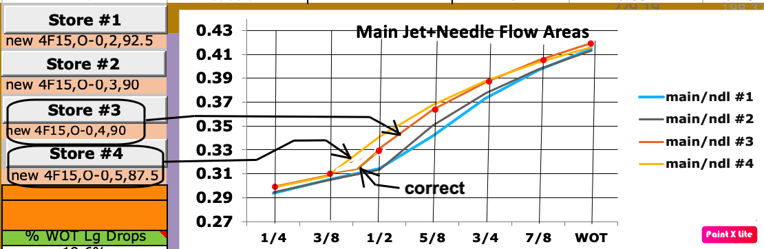
This graph is further explained in THIS VIDEO. Using it is an alternative method to seeing jetting changes due to changes in the needle, needle jet, needle clip position, and main jet.
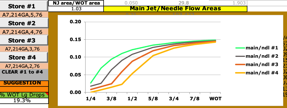
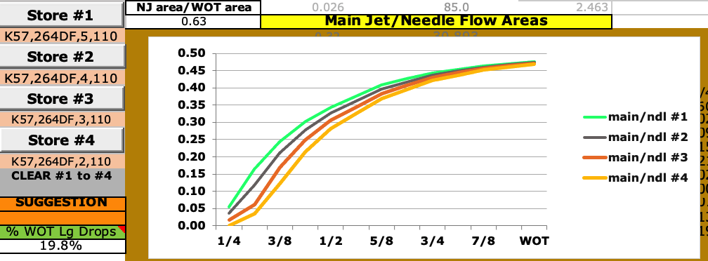
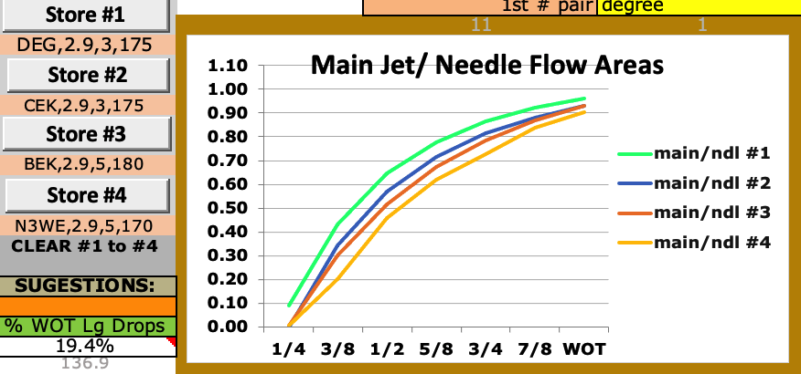
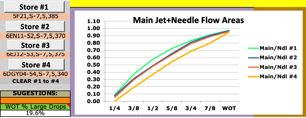
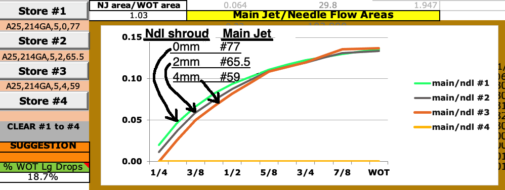
The graph always starts at 0 just to make them more visible. The data for these 4 graphs come from cells C14 to I14 and the true flow areas of C14 are listed for #1 to #4 graphs just above the chart. So in this example #1 has .529 which is 7% more than the .494 of #4 so it causes 7% more richness at 1/4 slide open. 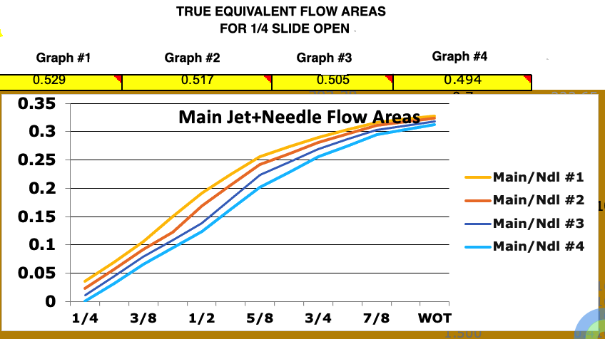 |