| This is a 6 page pdf file that needs to be printed out. Then cut along the outside of each pattern. Then place each one on top of .7mm - .8mm (22 gauge sheet metal, non-galvanized) and draw around it with a marks-a-lot. Then use metal shears to cut along the inside of the markings on the sheet metal to cut out the pattern. Then manually roll each section according to this video. Then have it welded together. Recommended is TIG, MIG, oxy-acetylene. It can be done with electric arc welding but it looks terrible and leaves a lot of little pinhole leaks. But the pipe would work as long as you didn't let metal drool inside the first two welds of the diffuser (w/o grinding the excess metal down inside the pipe). The 6th page (not pictured here) is for a dual coned diffuser which is more desirable than a 3 cone when using a non-reed piston port intake. I found by testing that a properly ported piston port intake engine can perform just as well as a reed valved engine. See my video on the subject. Every pipe has to be matched to porting, no exception. Learn how to port by watching my videos and reading my porting info on this site. Very Important! First learn how to measure the current engine port durations. Here's my porting page: [link] Choose one of these porting duration sets for the max RPM you want. For engines with reed valves (and windowed piston) ignore the intake durations. 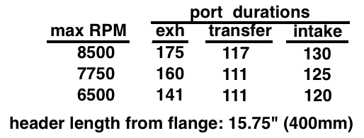 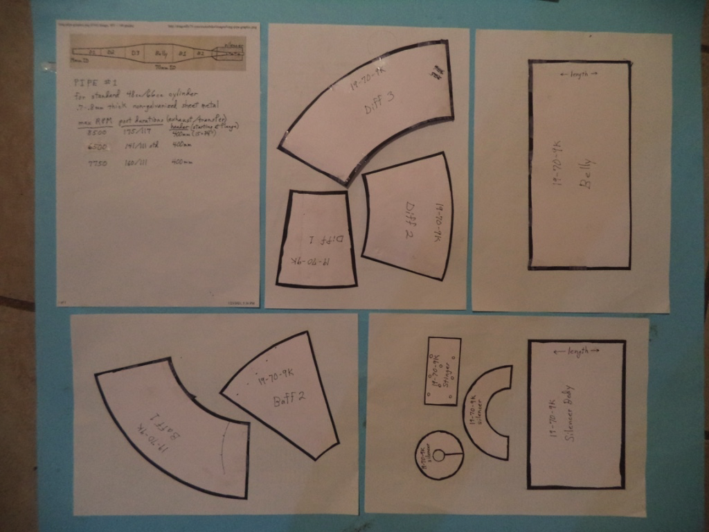 This is a straight pipe for a 19mm (3/4") inner diameter header which is standard for the 48cc and 66cc (often wrongfully called an 80cc). Email me at 19jaguar75@gmail.com if interested in buying the patterns. 19mm inner diameter tubing is available on-line from www.metalsdepot.com (#T278065) but it's much cheaper at Home Depot (in USA, size 3/4" ID x 1/16" wall thickness x 3 foot long for $10.50). But you normally don't need any extra tubing as long as you are careful to cut the header the right length. This is the pipe, completely straight which is easiest to build and gives the best power. Top RPM is a function of the exhaust port duration and length of pipe. To acheive a higher duration you use a rotary tool and cutting discs to raise the port. Using my 2 stroke software I figured out the right combinations of durations and the header lengths for the best powerbands. 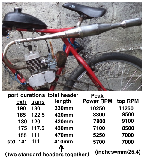 For a 66cc the ideal header inner diameter is 23mm which is .9" so if you want the absolute best power for your 66cc then you can make your own header out of .93 inch inner diameter tubing (McMaster-Carr #89895K767 $19). Then for the 3 cone diffuser to match you will need to cut off the first 70mm of it and make the header 70mm longer. (Stinger size remains the same for both engines.) Or for the 2 cone diffuser cut off the beginning 38mm of the diffuser and increase the header length by the same amount. 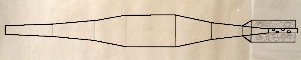 For a long curved header like what I have, just cut the curved section off of a $17 standard exhaust pipe and have that welded onto the existing header (after the muffler has been hack-sawed off of both). That can be seen by looking at my bike pics. 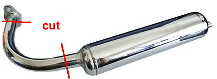 Simple Silencer My recommended silencer, outlined in the pipe pattern, gives the most noise reduction but I tried a pipe with the simple silencer and it wasn't too too loud. Just drill eight 1/8" holes in the end plate near the outer edge. For a 10mm ID stinger you can roll your own from sheet metal or buy from McMaster-Carr #8985K481 4"/$6.38 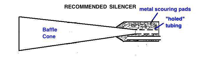 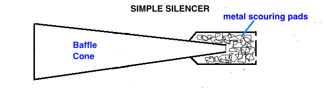 Questions & Answers Will this work on other cylinders? Yes as long as you make the header length match the exhaust duration. And then cut the diffuser to match your header diameter and increase the header length by the sme distance. What if my durations don't match anything you've listed? Just use my formula for finding the top RPM of the pipe according to the exhaust duration. It's on the previous page. The transfer duration is the main factor determining the peak power RPM of the porting which should be 1750 RPM less than the top pipe RPM if you want a broad powerband, or 750 RPM less if you want the best peak power. How is the weight of the pipe supported? Look closely at the picture to see the hose clamp right at the beginning of the belly holding it against the frame. Why the two hose clamps at the end of your header? That is to allow me to connect different pipes for testing purposes. I'm always learning new tricks and like the ability to do a quick change. |