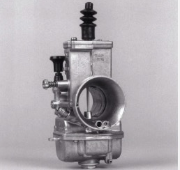
Jetting Mikuni TMS/TMX carburetors
At the bottom of this page are the links to the needle and needle jet info that you will need to know, such as the inner diameter of the needle jet of your carb. Starting at row 51 of the TMX sheet are all the needles and their data.
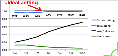
The 2nd graph to the right is an easier/quicker way to try to change the jetting if you have a good idea of how the jetting is at low throttle and 5/8 slide open (a little more than half throttle). Both methods here first require that you follow my advice for finding the right idle jetting and WOT jetting. Click here to read about this method.
1) First make sure your real life idle jet size is correct. Turn in the slide stop screw till you have a slightly fast idle. Then slowly turn the air screw till you find where it idles the fastest, then readjust the slide stop for the same fast idle as before if it has changed. Then slowly turn clockwise the air screw till the idle speed starts to drop off due to starting to be too rich (but which is good for starting w/o the choke in warm weather). This should result to be within 1 to 2 turns out. If it is less than 1 turn then you need a bigger idle jet. If it is more than 2 turns then you need a smaller idle jet. Install the correct idle jet if necessary and repeat procedure, adjusting the idle air screw. Then turn the slide stop screw till you have a normal idle speed. The right idle jet is what gives these two things: 1) the most consistent idling when the engine is hot, 2) the best off-idle power as you open the throttle slowly (although the needle clearance is just as important). Later you can change the slide stop position, idle jet, and air screw setting to your own preference, the best example being that racers let the slide low enough for engine braking that is too low to allow the engine to idle. Normally if you have to make the idle mixture too rich for smooth idling in order to help compensate for weak throttle response as you crack the throttle open then you either have the needle clip in too high a position (lowered needle), the needle is too fat, or the needle jet (the brass hole the needle slides into) is too narrow.
2) Make sure your main jet is correct. The simplest method is to try a few jets and pick the richest one that allows clean WOT running. The most correct method is testing acceleration times to find the jet size that allows the best acceleration. Click here to find out the best way to size the main jet.
|
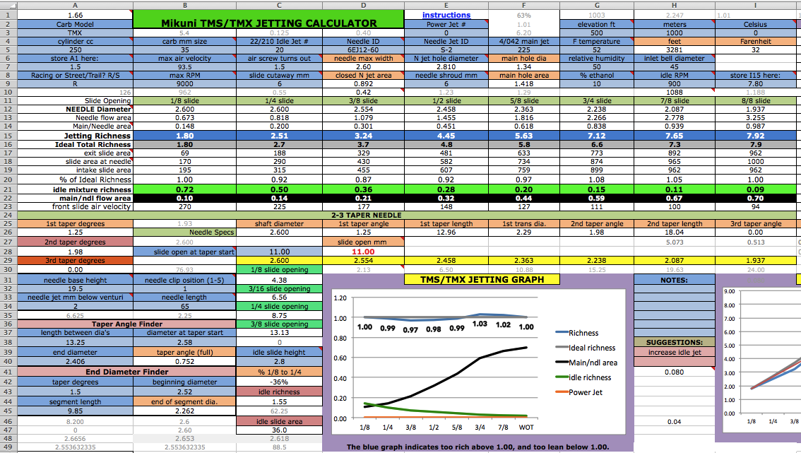
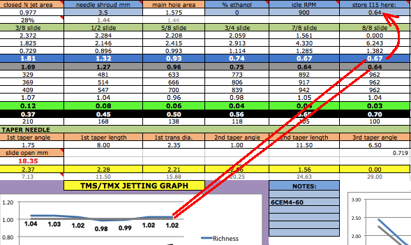
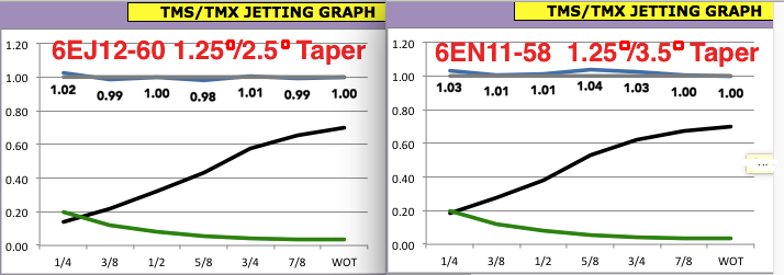
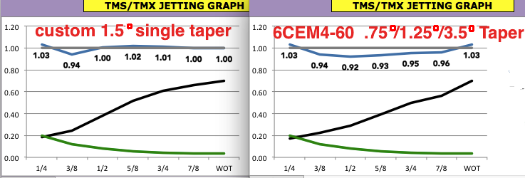
Reading the graph: If this program was perfect then the gray line would represent the perfect reference point to compare the calculated jetting to. But it isn't perfect so you need to know beforehand how you want to change the jetting. You should note the #s of the blue line at the different slide openings and then make the changes to the needle and main jet to make the blue graph vary from the previous graph the way you are intending. In this example maybe the engine really is too rich at 1/2 open for trail riding and so the virtual changes would be trying to bring down the 1/2 open # from 1.08 to at least 1.06. |
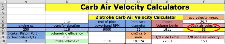
3) Go to the last sheet (velocity tab) to find out the carb air velocity you'll need to enter at B7 of the TMX sheet. If you aren't sure of the transfers duration then enter 125-130 for race engines or 115-120 for street/trail engines.
4) Enter the 4/042 main jet # at F5 on the TMX sheet.
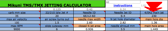
5) At D5 you enter the needle ID (code) so the program can find the needle in the listing farther down the same sheet and use its data for the calculations. The ID is imprinted near the top of each needle. Data for a custom needle can be entered at rows 88- 91 if its needle data is missing. Give any custom needle a unique ID.
|
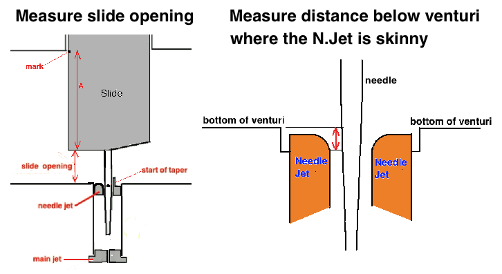
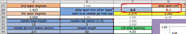
6) Enter at C28 the millimeters the slide is open when the start of the needle taper is at the top of the narrow section of its jet. You can use the manual method described on the previous page. At D28 the slide height is calculated so you can use that. That depends on the needle specs as well as the data you enter at A32, B32, A34, B34. But the most accurate way is measuring it if you have a digital caliper. One of my videos shows me measuring it. Normally the needles are 34mm plus the taper length but you need to measure it from top to bottom, excluding the little end cones. |
 |
7) Adjusting the end of the "ideal jetting" grey graph. Look at the graph results to see where the blue graph is above or below the grey line at full slide opening (far right). If you know the main jet size was selected for best power then enter the value from I15 into I9.
I9 sets the height of the end of the grey line (which represents perfect jetting which your calculated jetting is compared to). In this example 65 needs to be entered at I9. If you know the bikes jetting is a tad rich then subtract 4% from I15 and enter that at I9. Vice reversa if it's running a tad lean. The beginning and end of the gray graph are important to set because between those two points the graph follows a predetermined line which won't be correct if the start or end isn't correct.
| 8) Now set the beginning of the "ideal jetting" gray graph. If your idle air screw is correctly adjusted and you have measured the idle slide height and entered it at C40, then enter the value of A1 at A7 (5.12 in this example). This will set the beginning of the grey graph in case you virtually make any changes that affect idle jetting (idle jet, air screw, shroud height, cutaway) so the graph will show how far off it is from ideal. The beginning and end of the gray graph are the most important to set. | 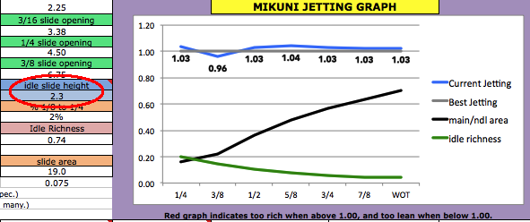 |
If the beginning graph is off from reality (blue too high or too low) then change the # at A7 to make it represent what you are feeling when reving and riding it. This will compensate for any bad measurements you've made or the idle circuit design varying from what is expected by the formulas.
| Virtually Finding The Best Jetting 9) If you want to lower the blue jetting graph from 1/4 to 5/8 slide open then you'll need to 1) raise the needle clip # at B32 for a lower # at D28 to enter at C28, or 2) reduce the clearance between needle and needle jet by selecting a needle with fatter diameter or a needle jet with smaller diameter. If the graph there is too lean then you need the opposite. That change also affects idle and main jetting and so the number at A1 will change. When that happens then change the air screw turns or idle jet # till A1 returns to what you recorded before at A7. You can also lower the needle shroud height (and increase the main jet) to lessen the graph from 1/4 to 7/8. Also less slide cutaway makes the jetting there richer. Additionally you can lower the slide opening at C28 (by lowering the needle clip) to raise the beginning section of the blue graph to be closer to the ideal grey graph. If that exceeds the physical limitations of the slide and needle clip then you can put home-made washers under the needle clip to reduce the slide opening at taper start. Then measure the new distance and enter that value at C28. |
|
10) Selecting a different needle taper. Notice the blue graph at 1/2 to 5/8 slide opening and if it is above the grey graph by very much then you need a different needle with a smaller taper angle. If the blue graph is below the grey one then the needle needs a larger taper angle. |
 |
How Many Tapers?
Triple-tapered needles are just a bad idea. Look at how they screw up the flow area graph.
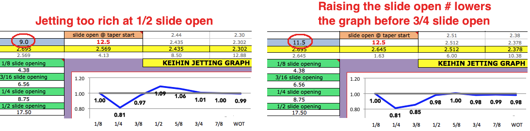
11) After everthing is done, and the graph shows too lean or rich mid throttle than what you experience, then you'll need to adjust the graph with an adjustment factor at A9. 1 doesn't change it at all but higher than that (up till the max listed at A10) will bow upward the graph before WOT. This page tells the correct procedure for evaluating the jetting.
12) Re-record this spreadsheet with all of your data in it. For example, if saving data for a YZ250 then save it as JettingCalcYZ250.xlsm
Here's what the carbs usually come equipped with:
TMX + TMS needles:
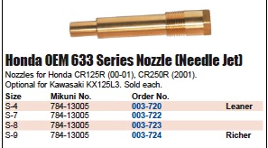
If you aren't sure what needle jet is in your carb then you'll have to get an idea what size opening the needle jet has by inserting different size drill bits into it unless of course you can unscrew it from the carb. What SUDCO stocks is series 633 S-4/7/8/9, and series 914 S-9.

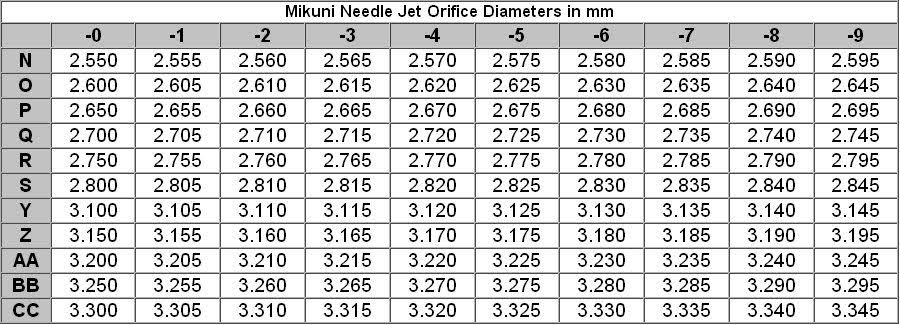
This is from the Jets R Us website concerning needle jets for the TMX. S-7 has an inner diameter of 2.835mm so if your needle jet is not removable and is impossible to measure then just use that diameter by entering S-7 at E5. That should be close enough to reality.
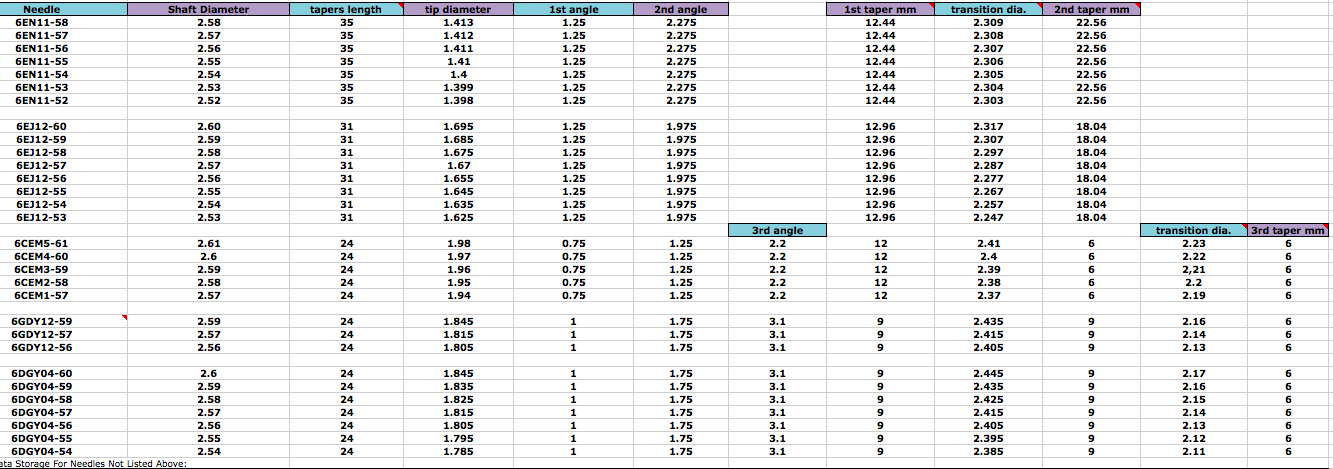
TMS/TMX Needles from Jets-R-Us:
EARLY STYLE TMX35 FLATSLIDE: 6EN11-(52/53/54/55/56/57/58) $7.04
EARLY STYLE TMX38 FLATSLIDE: 6EJ12-(53/54/55/56/57/58/59/60) $7.04
TMS38-77, 78 125cc: 6GDY12-(56/57/59) $7.04
TMS38-77, 78 250cc: 6DGY04-(54/55/56/57/58/59/60) $7.04
TMS 38-78: 6CEM(01/02/03/04/05) $12.04
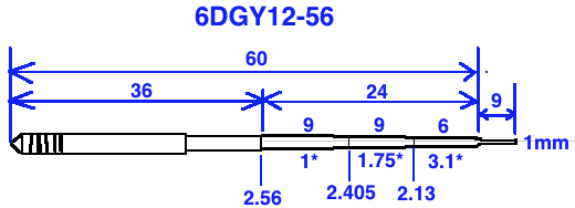
Example Mikuni TMS needle: 6DEY26-66
The first 6 is the length, which in this case is more than 60mm but less than 70mm
The -66 translates to the straight part of the needle. Divide it by 100 and add to 2 so that 66 = 2.66mm in diameter. And 6DEY26-67 = 2.67mm dia.
Other options:
6DEY27-66 is a 1/2 clip richer than a 6DEY26-66
Letters DEY indicate triple taper needle. D=1 degree taper, E=1.25 degree, Y=3.1 degree. A=0.25 degrees and increase by .25 degrees per letter increase till G, thereafter the letter increase is .075mm each. Two letters indicates dual taper, and three letters indicates three tapers.
Below are all the hidden comments for you to see if your computer won't let you see all of them in the spreadsheet:
Cell - Comment
E2 - The Mikuni Power Jet uses the same #/diameter system as the N100/604 Main Jets. If you don't have a power jet then leave this entry as 0. Don't forget entering the needed data at B113 if you have a power jet. The hole area of the power jet is listed at A1. The normal range for it is between 1.5x and 2x the area difference between the before and after main jets [area listed at F9].
G2 - feet elevation from sea level of riding area
H2 - This is optional for you to be able to convert meters elevation to feet.
I2 - This is optional for you to be able to convert Celsius to Farenheit.
AE2 - The average inner diameter between the front of the carb slide and the beginning of the reed valve (or intake port if the engine is piston port intake). For most reed valve engines this is just the carb size since that frontal carb extension usually has the same inner diameter as the carb bore at the slide. If you leave this blank then the program will assume its the same size as the carb.
C3 - Idle jet hole area
B4 - Throat diameter in millimeters
D4 - This is used by the program to look up the needle specs from the listed needles starting at A52. You can enter a new needle with its specs at row 88 or 90.
G4 - riding temperature in farenheit
A6 - Enter 1.0 if the 1st half of throttle opening causes clean running with good acceleration when slowly opening the throttle. Enter higher than 1.0 for richer jetting (sputtering a bit at steady low throttle), or lower for leaner jetting (tendency to bog when quickly opening the throttle). This depends on your riding experience. Set this number to show on the jetting graph that the 2nd to 4th graph numbers represent what you feel when testing the low throttle jetting. Ignore the 1st number because that is just off idle and you blow right past that, even when slowly opening the throttle. After changing this you'll need to enter the # of A1 into A5.
B6 - This is from velocity sheet, F7 for 2 stroke or F34 for 4 stroke.
C6 - 1 to 2 is the most effective range
D6 - Needle shaft width at straight portion.
E6 - Needle jet hole diameter
H6 - This is the diameter at the intake bell with the air intake hole (that leads to the air screw) middle being at the outer diameter. The cross sectional area there is more than inside the carb venturi which makes the air velocity there less which makes the suction at that hole less.
I6 - Measure the slide height right at the sides of the center hole in the slide that accommodates the needle shroud. To the right, under column P, is a photo showing this.
A8 - Entering a number higher than 1 will show the jetting between 1/8 slide and WOT to be richer. So you can adjust the graph to show what you feel it is doing when you ride. For a full explanation of how to judge your jetting just go to dragonfly75.com/moto/carbtuning.html
Number 1 keeps the graph unchanged.
B8 - End of pipe powerband RPM
C8 - The cutaway height in the middle of its arc in millimeters. When this is changed then the # at I7 also needs to be changed after measuring.
D8 - the area between the needle shaft and the needle jet
E8 - height of needle shroud above bottom level of venturi.
G8 - % ethanol in gasoline. Use a $12 ethanol % tester if you don't know. Jetting needs change with different % of ethanol.
H8 - If you don't know your idle RPM then just enter 900.
I8 - Enter the # from I15 here if the WOT jetting is good. Do this before entering anything different from your current "best WOT jetting" setup.
C10 - air screw factor
D10 - This is a rating of the needle jet diameter and needle shroud based on their relation to the idle jet and main jet. Less than .8 means the needle jet is too small or the needle shroud is too low (or both). More than 1.3 means the needle jet is too large or the shroud is too high (or both).
E10 - Diameter of needle shroud.
H10 - This is an estimate of idle RPM just based on engine size.
A12 - Needle diameter at its jet at said slide opening
A14 - Composite main and needle flow area
A17 - The cross sectional area at the exit side of the slide
A18 - The open cross sectional area at the slide intake
K25 - This is dependent on the value at C28
O25 - # turns out at idle
O26 - calculated slide height at idle
D27 - Slide open mm @ taper start calculated from data you enter at A32 to B34. Use this at C28 or just measure by the method listed on my web site. "Increase C28" is the displayed message when the needle is too short for the # entered at C28 and the needle will pull out of its jet completely at WOT causing a sudden richness.
B28 - Use the # calculated at D28 after entering data at A32, B32, A34, B34. Or just measure the distance using my method outlined on my web site. Click "instructions" at E1.
K29 - Closed throttle needle jet area divided by combined raw flow area at WOT of needle jet and main jet. Larger than 0.8 means low throttle jetting will be too rich. Too large means the needle to needle jet clearance is too big and you need a fatter needle or skinnier needle jet.
D30 - Distance mm from taper start
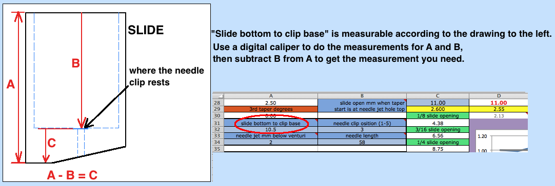
A31 - Height from bottom of slide to where the needle clip rests on. It is dimension C in the graphic below starting at A116.
B31 - #1 is the highest position and #5 is the lowest. After changing it be sure to enter the value from D28 into C28. If you put washers under the clip then add their thickness to B32.
A33 - Millimeters that the narrow part of the needle jet is below the level of the bottom of the venture.
B33 - Length from top to bottom of taper, not including the little end cones. Most are around 34mm + the listed taper length but you need to measure it.
C39 - Very Important! If this is wrong then it screws up the rest of the graph. I use small allen wrenches to measure the closed throttle slide opening. This opening has to be so that the engine is smoothly idling. For engine braking you might want this opening to be smaller but for this program you need to find the opening that allows smooth idle. After finding that then you can lower it back to where it was. Normal range of height is 8 to 12% of carb size. If it's so big that it causes B15 to be less than zero then it screws up the graph.
M41 - Size of each cylinder
H42 - % large fuel droplet amount of total fuel at WOT. These contribute to cooling and lubrication.
M44 - Idle jetting richness.
V50 - % large drops
C51 - combined tapers length
H51 - 1st taper length
I51 - where two tapers meet
J51 - 2nd taper length
K68 - where 2nd and 3rd tapers meet
L68 - 3rd taper length
A75 - GDY is mis-marked. It is also a DGY, same as those below.
C86 - combined tapers length
H86 - taper length
I86 - where 1st and 2nd tapers meet
J86 - 2nd taper length
K86 - where 2nd and 3rd tapers meet
L86 - 3rd taper length
E94 - combined tapers length
I94 - 1st taper length
J94 - diameter where two tapers meet
K94 - 2nd taper length
A112 - Distance from top of gasoline in the bowl (usually equal to top of bowl) to the top of the needle jet. Enter this value if you know it, otherwise leave A113 blank so the computer can use 17mm which is a typical value.
B112 - For power valves this is the distance in mm from the bottom of the venturi to the top middle of the highest location of the supply tube. Look at the picture to the right.
J134 - squaring factor for the air velocity at the power jet. The range is .7 to 2, with 2 being ideal when the jet outlet is right at the center of the flow area. The closer the outlet is to the outer edge of the flow area, the closer it should be to .7 which is because the speed and suction is lowest there.
A230 - extended to 0/8
A270 - Modified S+M drops at idle
A271 - extended to 0/8
A273 - gas/air at idle
A275 - extended to 0/8
A277 - extended to 0/8
A278 - ideal idle mix