|
About
Balancing Engines for Less Vibration An imbalance in the crankshaft in relation to the weight of piston assembly causes vibration and a loss of power. Making sure your engine is balanced correctly is essential, especially if you are modifying the engine to work in a different RPM range than what it was designed for. When the piston goes to TDC and then is pulled back down by the crank, the force on the crankshaft is towards the cylinder head because that changing of direction creates a force of inertia upwards. Put any weight on a string and throw it away from you and then jerk it back to you and feel the outward force. Same thing. And the same thing happens at BDC. Those up and down forces create vibration. But that is countered by having holes in the crank wheels close to the conrod pin. The only problem is that the holes then allow a perpendicular forward and reverse force to act on the crankshaft due to the unbalanced crank wheels. So a "balanced" engine has crank wheel holes just the right size to create the least amount of vibration. But since those forces peak every 90 degrees of crank rotation then basically the end result is a kind of triangle of forces. The graphs below are from my crank balance calculator. In this set of 3 RPM graphs the middle one is when the engine starts to feel more vibration than at lower RPM. The downward depression of the "triangle" top, mostly visible in the left graph, is due to the combustion force. The higher the engine compression the more the upwards forces are countered, mostly after TDC. Also the smaller the engine, the more the compression can change the balance. The second row of 3 graphs is the same but I colored the parts of the graphs where the program averages the radial forces. In this example the averge sets of forces at 5100 are 65 and 69 for a ratio of .95, and at 6200 are both 98 for a ratio of 1.0, and at 7400 are 149 and 139 for a ratio of 1.04. So the program is set by me to read those sections of forces to be compared to each other. When the "near TDC" forces start to excedd the "pre-BDC" forces is when vibration starts increasing. 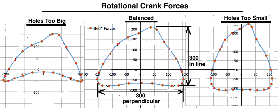 Here's the V/H balance blue graph, and how it is (red graph) after factoring in the change in radial force average of each RPM. This explains how it can basically feel almost balanced at low RPM although it isn't. You just don't feel the imbalance because the forces are smaller. 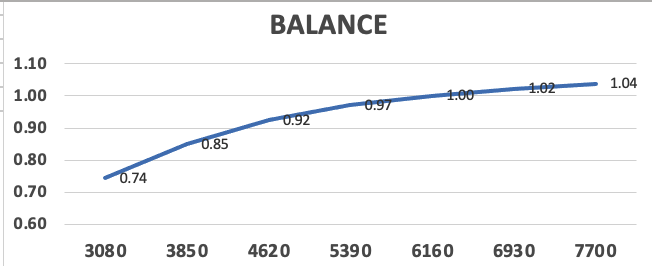 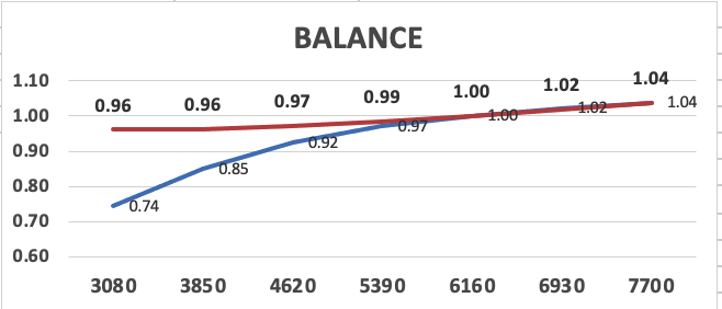 Click here to read why I don't recommend using the balance factor method.
Click here to read of my tests which helped me develop my crank balance program. centrifugal force calculator (don't
enter linear speed. change m to mm, change kg to grams, change N
to lbf) Here
is a picture of my crank assembly with an additional balancing hole
just above the conrod pin. The 6 blue holes are lightening holes (although I wouldn't recommend any more than 4 if
the bike is for street use). The blue is foam filling half the hole.
The ends of each hole were later filled with JBWeld. I used foam just
to reduce the amount of expensive JBWeld used. The conrod hole and two
factory balance holes are already filled with JBWeld for increased
crankcase compression (although the change is very small).  You can drill extra balance holes
with any good electric drill although it's a bit tough. Much easier to
take it to a machine shop and let them put it on a drill press. Also
the holes can be drilled at the TDC or BDC location of the crank wheels
without even taking it out of the crank cases. Just put duct tape on
the crank wheels (after cleaning them with alcohol) to keep metal
shavings from going into the crankcase, and then keep the crank in
correct position by using vise grips on the primary gear above and
below where it meshes with the clutch gear. You can measure from
halfway through the angled drill bit tip and mark the drill bit at the correct
distance with black electrical tape wrapped around it. That way you have a visual
reference while drilling. Here's one of my cranks with holes drilled 180 degrees from the crank pin: 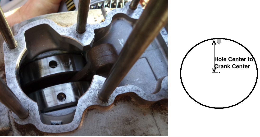 DIY Crank Balance Test:  Click here to read more about my spreadsheet which can be used to calculate the size of counter balance holes needed in any single cylinder crank (2 stroke or 4 stroke). |